本文档旨在为方便起见,提供有关
TI产品中文版本的信息,以确认产品的概要.
有关适用的官方英文版本的最新信息,请访问www.
ti.
com,其内容始终优先.
TI不保证翻译的准确性和有效性.
在实际设计之前,请务必参考最新版本的英文版本.
EnglishDataSheet:SLVS892TPS61175ZHCSJF8F–DECEMBER2008–REVISEDAPRIL2019具具有有软软启启动动功功能能和和可可编编程程开开关关频频率率的的TPS611753A高高压压升升压压转转换换器器11特特性性12.
9V至18V输入电压范围3A、40V内部开关高效电源转换:效率高达93%可由外部电阻器设置的频率范围:200kHz至2.
2MHz同步外部开关频率用户定义的软启动至满负载负载较轻时用于输出调节的跳跃开关周期14引脚HTSSOP封装-带PowerPad使用TPS61175以及WEBENCH电源设计器创建定制设计2应应用用5V至12V、24V功率转换支持SEPIC和反激式拓扑结构ADSL调制解调器电视调谐器3说说明明TPS61175是一款具有集成式3A、40V电源开关的单片开关稳压器.
此器件可配置成多种标准开关稳压器拓扑,包括升压、SEPIC和反激式.
该器件具有宽输入电压范围,可支持输入电压来自多节电池或者5V、12V稳压电源轨的应用.
TPS61175使用电流模式脉宽调制(PWM)控制来调节输出电压.
PWM的开关频率由一个外部电阻器或一个外部时钟信号设定.
用户可以在200kHz至2.
2MHz之间对开关频率进行设定.
该器件具有可编程软启动功能,用于限制启动时的浪涌电流,并且还具有其他内置保护特性,如逐脉冲过流限制和热关断.
TPS61175采用带PowerPad的14引脚HTSSOP封装.
器器件件信信息息(1)器器件件型型号号封封装装封封装装尺尺寸寸((标标称称值值))TPS61175HTSSOP(14)5.
00mm*4.
40mm(1)如需了解所有可用封装,请参阅产品说明书末尾的可订购产品附录.
简简化化原原理理图图2TPS61175ZHCSJF8F–DECEMBER2008–REVISEDAPRIL2019www.
ti.
com.
cnCopyright2008–2019,TexasInstrumentsIncorporated目目录录1特特性性.
12应应用用.
13说说明明.
14修修订订历历史史记记录录25PinConfigurationandFunctions.
36Specifications.
46.
1AbsoluteMaximumRatings46.
2ESDRatings.
46.
3RecommendedOperatingConditions.
46.
4ThermalInformation.
56.
5ElectricalCharacteristics.
56.
6TypicalCharacteristics.
67DetailedDescription87.
1Overview87.
2FunctionalBlockDiagram87.
3FeatureDescription.
97.
4DeviceFunctionalModes.
118ApplicationandImplementation128.
1ApplicationInformation.
128.
2TypicalApplication129PowerSupplyRecommendations.
2010Layout.
2010.
1LayoutGuidelines2010.
2LayoutExample2010.
3ThermalConsiderations.
2111器器件件和和文文档档支支持持2211.
1器件支持.
2211.
2开发支持.
2211.
3接收文档更新通知2211.
4社区资源.
2211.
5商标.
2211.
6静电放电警告.
2211.
7Glossary.
2212机机械械、、封封装装和和可可订订购购信信息息.
234修修订订历历史史记记录录ChangesfromRevisionE(February2019)toRevisionFPage已更改SoftStartfigurereferencetopointtothecorrectsoftstartwaveform.
9已更改"≤"signin公式7to14ChangesfromRevisionD(April2016)toRevisionEPageChangedHandingRatingstabletoESDRatings;movedStorageTemperaturetoAbsoluteMaximumRatings4UpdatedsymbolsinThermalInformation5已添加theIIN(MAX)fortheIOUT(max)calculationequation.
14ChangesfromRevisionC(August2014)toRevisionDPageRevisedsecondparagraphofMinimumONTimeandPulseSkippingsectionorclarity.
11ChangesfromRevisionB(February2012)toRevisionCPage已添加处理额定值表,特性说明部分、器件功能模式、应用和实施部分、电源建议部分、布局部分、器件和文档支持部分以及机械、封装和可订购信息部分1ChangesfromRevisionA(October2010)toRevisionBPageReplacedtheDissipationRatingsTablewiththeThermalInformationTable.
4ChangesfromOriginal(December2008)toRevisionAPage已更改将订购信息表-器件型号从TPS61175更改为TPS61175PWP;删除了"封装标记"列13TPS61175www.
ti.
com.
cnZHCSJF8F–DECEMBER2008–REVISEDAPRIL2019Copyright2008–2019,TexasInstrumentsIncorporated5PinConfigurationandFunctionsTSSOP14PinsTopViewPinFunctionsPINI/ODESCRIPTIONNAMENO.
AGND7ISignalgroundoftheICCOMP8OOutputoftheinternaltransconductanceerroramplifier.
AnexternalRCnetworkisconnectedtothispintocompensatetheregulator.
EN4IEnablepin.
Whenthevoltageofthispinfallsbelowtheenablethresholdformorethan10ms,theICturnsoff.
FB9IFeedbackpinforpositivevoltageregulation.
Connecttothecentertapofaresistordividertoprogramtheoutputvoltage.
FREQ10OSwitchfrequencyprogrampin.
Anexternalresistorisconnectedtothispintosetswitchfrequency.
SeeapplicationsectionforinformationonhowtosizetheFREQresistor.
NC11IReservedpin.
Mustconnectthispintoground.
PGND12,13,14IPowergroundoftheIC.
ItisconnectedtothesourceofthePWMswitch.
SS5OSoftstartprogrammingpin.
AcapacitorbetweentheSSpinandGNDpinprogramssoftstarttiming.
SeeApplicationandImplementationforinformationonhowtosizetheSScapacitor.
SW1,2IThisistheswitchingnodeoftheIC.
ConnectSWtotheswitchedsideoftheinductor.
SYNC6ISwitchfrequencysynchronouspin.
CustomerscanuseanexternalsignaltosettheICswitchfrequencybetween200-kHzand2.
2-MHz.
Ifnotused,thispinshouldbetiedtoAGNDasshortaspossibletoavoidnoisecoupling.
ThermalPadThethermalpadshouldbesolderedtotheanalogground.
Ifpossible,usethermalviatoconnecttotopandinternalgroundplanelayersforidealpowerdissipation.
VIN3ITheinputsupplypinfortheIC.
ConnectVINtoasupplyvoltagebetween2.
9Vand18V.
ItisacceptableforthevoltageonthepintobedifferentfromtheboostpowerstageinputforapplicationsrequiringvoltagebeyondVINrange.
4TPS61175ZHCSJF8F–DECEMBER2008–REVISEDAPRIL2019www.
ti.
com.
cnCopyright2008–2019,TexasInstrumentsIncorporated(1)Stressesbeyondthoselistedunderabsolutemaximumratingsmaycausepermanentdamagetothedevice.
Thesearestressratingsonlyandfunctionaloperationofthedeviceattheseoranyotherconditionsbeyondthoseindicatedunderrecommendedoperatingconditionsisnotimplied.
Exposuretoabsolute-maximum-ratedconditionsforextendedperiodsmayaffectdevicereliability.
(2)Allvoltagevaluesarewithrespecttonetworkgroundterminal.
6Specifications6.
1AbsoluteMaximumRatingsoveroperatingfree-airtemperaturerange(unlessotherwisenoted)(1)MINMAXUNITSupplyvoltagesonpinVIN(2)–0.
320VVoltagesonpinsEN(2)–0.
320VVoltageonpinFB,FREQandCOMP(2)–0.
33VVoltageonpinSYNC,SS(2)–0.
37VVoltageonpinSW(2)–0.
340VContinuouspowerdissipationSeeThermalInformationOperatingjunctiontemperaturerange–40150°CStoragetemperature,Tstg–65150°C(1)JEDECdocumentJEP155statesthat500-VHBMallowssafemanufacturingwithastandardESDcontrolprocess.
(2)JEDECdocumentJEP157statesthat250-VCDMallowssafemanufacturingwithastandardESDcontrolprocess.
6.
2ESDRatingsVALUEUNITV(ESD)ElectrostaticdischargeHuman-bodymodel(HBM),perANSI/ESDA/JEDECJS-001(1)±2000VCharged-devicemodel(CDM),perJEDECspecificationJESD22-C101(2)±500(1)Theinductancevaluedependsontheswitchingfrequencyandendapplication.
Whilelargervaluesmaybeused,valuesbetween4.
7-μHand47-μHhavebeensuccessfullytestedinvariousapplications.
RefertoSelectingtheInductorfordetail.
6.
3RecommendedOperatingConditionsoveroperatingfree-airtemperaturerange(unlessotherwisenoted)MINNOMMAXUNITVINInputvoltage2.
918VVOOutputvoltageVIN38VLInductor(1)4.
747μHfSWSwitchingfrequency2002200kHzCIInputcapacitor4.
7μFCOOutputcapacitor4.
7μFVSYNExternalswitchingfrequencylogic5VTAOperatingambienttemperature–4085°CTJOperatingjunctiontemperature–40125°C5TPS61175www.
ti.
com.
cnZHCSJF8F–DECEMBER2008–REVISEDAPRIL2019版权2008–2019,TexasInstrumentsIncorporated(1)有关传统和新热指标的更多信息,请参见应用报告《半导体和IC封装热指标》(文献编号:SPRA953).
6.
4ThermalInformationTHERMALMETRIC(1)TPS61175UNITPWP(HTSSOP)14PINSRθJAJunction-to-ambientthermalresistance45.
2°C/WRθJC(top)Junction-to-case(top)thermalresistance34.
9°C/WRθJBJunction-to-boardthermalresistance30.
1°C/WψJTJunction-to-topcharacterizationparameter1.
5°C/WψJBJunction-to-boardcharacterizationparameter29.
9°C/WRθJC(bot)Junction-to-case(bottom)thermalresistance5.
8°C/W6.
5ElectricalCharacteristicsFSW=1.
2MHz(Rfreq=80k),VIN=3.
6V,TA=–40°Cto+85°C,typicalvaluesareatTA=25°C(unlessotherwisenoted)PARAMETERTESTCONDITIONSMINTYPMAXUNITSUPPLYCURRENTVINInputvoltagerange2.
918VIQOperatingquiescentcurrentintoVinDevicePWMswitchingwithoutload3.
5mAISDShutdowncurrentEN=GND1.
5μAVUVLOUnder-voltagelockoutthreshold2.
52.
7VVhysUnder-voltagelockouthysteresis130mVENABLEANDREFERENCECONTROLVenhENlogichighvoltageVIN=2.
9Vto18V1.
2VVenlENlogiclowvoltageVIN=2.
9Vto18V0.
4VVSYNhSYNlogichighvoltage1.
2VSYNlSYNlogiclowvoltage0.
4VRenENpulldownresistor4008001600kToffShutdowndelay,SSdischargeENhightolow10msVOLTAGEANDCURRENTCONTROLVREFVoltagefeedbackregulationvoltage1.
2041.
2291.
254VIFBVoltagefeedbackinputbiascurrent200nAIsinkComppinsinkcurrentVFB=VREF+200mV,VCOMP=1V50μAIsourceComppinsourcecurrentVFB=VREF–200mV,VCOMP=1V130μAVCCLPComppinclampvoltageHighClamp,VFB=1VLowClamp,VFB=1.
5V30.
75VVCTHComppinthresholdDutycycle=0%0.
95VGeaErroramplifiertransconductance240340440μmhoReaErroramplifieroutputresistance10MfeaErroramplifiercrossoverfrequency500KHz6TPS61175ZHCSJF8F–DECEMBER2008–REVISEDAPRIL2019www.
ti.
com.
cn版权2008–2019,TexasInstrumentsIncorporatedElectricalCharacteristics(接接下下页页)FSW=1.
2MHz(Rfreq=80k),VIN=3.
6V,TA=–40°Cto+85°C,typicalvaluesareatTA=25°C(unlessotherwisenoted)PARAMETERTESTCONDITIONSMINTYPMAXUNITFREQUENCYfSOscillatorfrequencyRfreq=480k0.
160.
210.
26MHzRfreq=80k1.
01.
21.
4Rfreq=40k1.
762.
22.
64DmaxMaximumdutycycleVFB=1V,Rfreq=80k89%93%VFREQFREQpinvoltage1.
229VTmin_onMinimumonpulsewidthRfreq=80k60nsPOWERSWITCHRDS(ON)N-channelMOSFETon-resistanceVIN=VGS=3.
6VVIN=VGS=3.
0V0.
130.
130.
250.
3ILN_NFETN-channelleakagecurrentVDS=40V,TA=25°C1μAOC,OVPANDSSILIMN-ChannelMOSFETcurrentlimitD=Dmax33.
85AISSSoftstartbiascurrentVss=0V6μATHERMALSHUTDOWNTshutdownThermalshutdownthreshold160°CThysteresisThermalshutdownthresholdhysteresis15°C6.
6TypicalCharacteristicsCircuitof图1;L1=D104C2-10μH;D1=SS3P6L-E3/86A,R4=80k,R3=10k,C4=22nF,C2=10μF;VIN=5V,VOUT=24V,IOUT=200mA(unlessotherwisenoted)表表1.
TableOfGraphsFIGUREEfficiencyVIN=5V,VOUT=12V,24V,35V图1EfficiencyVIN=5V,12V;VOUT=24V图2ErroramplifiertransconductancevsTemperature图3SwitchcurrentlimitvsTemperature图4SwitchcurrentlimitvsDutycycle图5FBaccuracyvsTemperature图6LinetransientresponseVIN=4.
5Vto5V图12LoadtransientresponseIOUT=100mAto300mA;referto'compensatingthecontrolloop'foroptimization图13PWMOperation图14PulseskippingNoload图15Start-upC3=47nF图167TPS61175www.
ti.
com.
cnZHCSJF8F–DECEMBER2008–REVISEDAPRIL2019版权2008–2019,TexasInstrumentsIncorporated图图1.
EfficiencyvsOutputCurrent图图2.
EfficiencyvsOutputCurrent图图3.
ErrorAmplifierTransconductancevsFree-AirTemperature图图4.
OvercurrentLimitvsDutyCycle图图5.
OvercurrentLimitvsFree-AirTemperature图图6.
FBVoltagevsFree-AirTemperature8TPS61175ZHCSJF8F–DECEMBER2008–REVISEDAPRIL2019www.
ti.
com.
cn版权2008–2019,TexasInstrumentsIncorporated7DetailedDescription7.
1OverviewTheTPS61175integratesa40-Vlow-sideswitchFETforupto38-Voutput.
Thedeviceregulatestheoutputwithcurrentmodepulsewidthmodulation(PWM)control.
ThePWMcontrolcircuitryturnsontheswitchatthebeginningofeachswitchingcycle.
Theinputvoltageisappliedacrosstheinductorandstorestheenergyasinductorcurrentrampsup.
Duringthisportionoftheswitchingcycle,theloadcurrentisprovidedbytheoutputcapacitor.
Whentheinductorcurrentrisestothethresholdsetbytheerroramplifieroutput,thepowerswitchturnsoffandtheexternalSchottkydiodeisforwardbiased.
Theinductortransfersstoredenergytoreplenishtheoutputcapacitorandsupplytheloadcurrent.
Thisoperationrepeatseacheveryswitchingcycle.
AsshowninFunctionalBlockDiagram,thedutycycleoftheconverterisdeterminedbythePWMcontrolcomparatorwhichcomparestheerroramplifieroutputandthecurrentsignal.
Theswitchingfrequencyisprogrammedbytheexternalresistororsynchronizedtoanexternalclocksignal.
Arampsignalfromtheoscillatorisaddedtothecurrentramptoprovideslopecompensation.
Slopecompensationisnecessarytoavoidsubharmonicoscillationthatisintrinsictothecurrentmodecontrolatdutycyclehigherthan50%.
Iftheinductorvalueislowerthan4.
7μH,theslopecompensationmaynotbeadequate.
ThefeedbackloopregulatestheFBpintoareferencevoltagethroughatransconductanceerroramplifier.
TheoutputoftheerroramplifierisconnectedtotheCOMPpin.
AnexternalRCcompensationnetworkisconnectedtotheCOMPpintooptimizethefeedbackloopforstabilityandtransientresponse.
7.
2FunctionalBlockDiagram9TPS61175www.
ti.
com.
cnZHCSJF8F–DECEMBER2008–REVISEDAPRIL2019版权2008–2019,TexasInstrumentsIncorporated7.
3FeatureDescription7.
3.
1SwitchingFrequencyTheswitchfrequencyissetbyaresistor(R4)connectedtotheFREQpinoftheTPS61175.
Donotleavethispinopen.
Aresistormustalwaysbeconnectedforproperoperation.
See表2and图7forresistorvaluesandcorrespondingfrequencies.
表表2.
SwitchingFrequencyvsExternalResistorR4(k)fSW(kHz)443240256400176600801200512000图图7.
SwitchingFrequencyvsExternalResistorAlternatively,theTPS61175switchingfrequencywillsynchronizetoanexternalclocksignalthatisappliedtotheSYNCpin.
Thelogicleveloftheexternalclockisshowninthespecificationtable.
Thedutycycleoftheclockisrecommendedintherangeof10%to90%.
TheresistoralsomustbeconnectedtotheFREQpinwhenICisswitchingbytheexternalclock.
Theexternalclockfrequencymustbewithin±20%ofthecorrespondingfrequencysetbytheresistor.
Forexample,ifthecorrespondingfrequencyassetbyaresistorontheFREQpinis1.
2-MHz,theexternalclocksignalshouldbeintherangeof0.
96MHzto1.
44MHz.
IftheexternalclocksignalishigherthanthefrequencypertheresistorontheFREQpin,themaximumdutycyclespecification(DMAX)shouldbeloweredby2%.
Forinstance,iftheresistorsetvalueis2.
5MHz,andtheexternalclockis3MHz,DMAXis87%insteadof89%.
7.
3.
2SoftStartTheTPS61175hasabuilt-insoftstartcircuitwhichsignificantlyreducesthestart-upcurrentspikeandoutputvoltageovershoot.
WhentheICisenabled,aninternalbiascurrent(6μAtypically)chargesacapacitor(C3)ontheSSpin.
ThevoltageatthecapacitorclampstheoutputoftheinternalerroramplifierthatdeterminesthedutycycleofPWMcontrol,therebytheinputinrushcurrentiseliminated.
Oncethecapacitorreaches1.
8V,thesoftstartcycleiscompletedandthesoft-startvoltagenolongerclampstheerroramplifieroutput.
Referto图16forthesoftstartwaveform.
See表3forC3andcorrespondingsoftstarttime.
A47-nFcapacitoreliminatestheoutputovershootandreducesthepeakinductorcurrentformostapplications.
10TPS61175ZHCSJF8F–DECEMBER2008–REVISEDAPRIL2019www.
ti.
com.
cn版权2008–2019,TexasInstrumentsIncorporated表表3.
Soft-StartTimevsC3VIN(V)VOUT(V)LOAD(A)COUT(μF)fSW(MHz)C3(nF)tSS(ms)OVERSHOT(mV)5240.
4101.
2474none100.
821012350.
61021006.
5none100.
4300WhentheENispulledlowfor10ms,theICentersshutdownandtheSScapacitordischargesthrougha5-kresistorforthenextsoftstart.
7.
3.
3OvercurrentProtectionTheTPS61175hasacycle-by-cycleovercurrentlimitprotectionthatturnsoffthepowerswitchoncetheinductorcurrentreachestheovercurrentlimitthreshold.
ThePWMcircuitryresetsitselfatthebeginningofthenextswitchcycle.
Duringanovercurrentevent,theoutputvoltagebeginstodroopasafunctionoftheloadontheoutput.
WhentheFBvoltagedropslowerthan0.
9V,theswitchingfrequencyisautomaticallyreducedto1/4ofthesetvalue.
Theswitchingfrequencydoesnotresetuntiltheovercurrentconditionisremoved.
Thisfeatureisdisabledduringsoftstart.
7.
3.
4EnableandThermalShutdownTheTPS61175entersshutdownwhentheENvoltageislessthan0.
4Vformorethan10ms.
Inshutdown,theinputsupplycurrentforthedeviceislessthan1.
5μA(maximum).
TheENpinhasaninternal800-kpulldownresistortodisablethedevicewhenitisfloating.
Aninternalthermalshutdownturnsoffthedevicewhenthetypicaljunctiontemperatureof160°Cisexceeded.
TheICrestartswhenthejunctiontemperaturedropsby15°C.
7.
3.
5UndervoltageLockout(UVLO)Anundervoltagelockoutcircuitpreventsmis-operationofthedeviceatinputvoltagesbelow2.
5-V(typical).
Whentheinputvoltageisbelowtheundervoltagethreshold,thedeviceremainsoff,andtheinternalswitchFETisturnedoff.
TheUVLOthresholdissetbelowminimumoperatingvoltageof2.
9VtoavoidanytransientVINdiptriggeringtheUVLOandcausingthedevicetoreset.
FortheinputvoltagesbetweenUVLOthresholdand2.
9V,thedeviceattemptstooperate,butthespecificationsarenotensured.
11TPS61175www.
ti.
com.
cnZHCSJF8F–DECEMBER2008–REVISEDAPRIL2019版权2008–2019,TexasInstrumentsIncorporated7.
4DeviceFunctionalModes7.
4.
1MinimumONTimeandPulseSkippingOncethePWMswitchisturnedon,theTPS61175hasminimumONpulsewidthof60ns.
ThissetsthelimitoftheminimumdutycycleofthePWMswitch,anditisindependentofthesetswitchingfrequency.
WhenoperatingconditionsresultintheTPS61175havingaminimumONpulsewidthlessthan60ns,theICenterspulse-skippingmode.
Inthismode,thedevicekeepsthepowerswitchoffforseveralswitchingcyclestokeeptheoutputvoltagefromrisingabovetheregulatedvoltage.
ThisoperationtypicallyoccursinlightloadconditionwhenthePWMoperatesindiscontinuousmode.
Pulseskippingincreasestheoutputvoltageripple,see图15.
Whensettingswitchingfrequencyhigherthan1.
2MHz,TIrecommendsusinganexternalsynchronousclockasswitchingfrequencytoensurepulse-skippingfunctionworksatlightload.
Whenusingtheinternalswitchingfrequencyabove1.
2MHz,thepulse-skippingoperationmaynotfunction.
Whenthepulse-skippingfunctiondoesnotworkatlightload,theTPS61175alwaysrunsinPWMmodewithminimumONpulsewidth.
Tokeeptheoutputvoltageinregulation,aminimumloadisrequired.
Theminimumloadisrelatedtotheinputvoltage,outputvoltage,switchingfrequency,externalinductorvalueandthemaximumvalueoftheminimumONpulsewidth.
Use公式1and公式2tocalculatetherequiredminimumloadattheworstcase.
Themaximumtmin_ONcouldbeestimatedto80ns.
CSWisthetotalparasitecapacitanceattheswitchingnodeSWpin.
Itcouldbeestimatedto100pF.
(1)(2)12TPS61175ZHCSJF8F–DECEMBER2008–REVISEDAPRIL2019www.
ti.
com.
cn版权2008–2019,TexasInstrumentsIncorporated8ApplicationandImplementation8.
1ApplicationInformationThefollowingsectionprovidesastep-by-stepdesignapproachforconfiguringtheTPS61175asavoltageregulatingboostconverter,asshownin图8.
WhenconfiguredasSEPICorflybackconverter,adifferentdesignapproachisrequired.
8.
2TypicalApplication图图8.
BoostConverterConfiguration8.
2.
1DesignRequirements表表4.
DesignParametersPARAMETERSVALUESInputvoltage5VOutputvoltage24VOperatingfrequency1.
2MHz8.
2.
2DetailedDesignProcedure8.
2.
2.
1CustomDesignwithWEBENCHToolsClickheretocreateacustomdesignusingtheTPS61175devicewiththeWEBENCHPowerDesigner.
1.
StartbyenteringyourVIN,VOUTandIOUTrequirements.
2.
Optimizeyourdesignforkeyparameterslikeefficiency,footprintandcostusingtheoptimizerdialandcomparethisdesignwithotherpossiblesolutionsfromTexasInstruments.
3.
WEBENCHPowerDesignerprovidesyouwithacustomizedschematicalongwithalistofmaterialswithrealtimepricingandcomponentavailability.
4.
Inmostcases,youwillalsobeableto:–Runelectricalsimulationstoseeimportantwaveformsandcircuitperformance,–Runthermalsimulationstounderstandthethermalperformanceofyourboard,–ExportyourcustomizedschematicandlayoutintopopularCADformats,–PrintPDFreportsforthedesign,andshareyourdesignwithcolleagues.
5.
GetmoreinformationaboutWEBENCHtoolsatwww.
ti.
com/webench.
13TPS61175www.
ti.
com.
cnZHCSJF8F–DECEMBER2008–REVISEDAPRIL2019版权2008–2019,TexasInstrumentsIncorporated8.
2.
2.
2DeterminingtheDutyCycleTheTPS61175hasamaximumworstcasedutycycleof89%andaminimumontimeof60ns.
Thesetwoconstraintsplacelimitationsontheoperatingfrequencythatcanbeusedforagiveninputtooutputconversionratio.
Thedutycycleatwhichtheconverteroperatesisdependentonthemodeinwhichtheconverterisrunning.
Iftheconverterisrunningindiscontinuousconductionmode(DCM),wheretheinductorcurrentrampstozeroattheendofeachcycle,thedutycyclevarieswithchangestotheloadmuchmorethanitdoeswhenrunningincontinuousconductionmode(CCM).
Incontinuousconductionmode,wheretheinductormaintainsadccurrent,thedutycycleisrelatedprimarilytotheinputandoutputvoltagesascomputedin公式3:(3)Indiscontinuousmodethedutycycleisafunctionoftheload,inputandoutputvoltages,inductanceandswitchingfrequencyascomputedin公式4:(4)Allconvertersusingadiodeasthefreewheelingorcatchcomponenthavealoadcurrentlevelatwhichtheytransitionfromdiscontinuousconductiontocontinuousconduction.
Thisisthepointwheretheinductorcurrentjustfallstozero.
Athigherloadcurrents,theinductorcurrentdoesnotfalltozerobutremainsflowinginapositivedirectionandassumesatrapezoidalwaveshapeasopposedtoatriangularwaveshape.
Thisloadboundarybetweendiscontinuousconductionandcontinuousconductioncanbefoundforasetofconverterparametersin公式5:(5)Forloadshigherthantheresultof公式5,thedutycycleisgivenby公式3andforloadslessthattheresultsof公式4,thedutycycleisgiven公式5.
For公式3through公式5,thevariabledefinitionsareasfollows:VOUTistheoutputvoltageoftheconverterinVVDistheforwardconductionvoltagedropacrosstherectifierorcatchdiodeinVVINistheinputvoltagetotheconverterinVIOUTistheoutputcurrentoftheconverterinAListheinductorvalueinHfSWistheswitchingfrequencyinHzUnlessotherwisestated,thedesignequationsthatfollowassumethattheconverterisrunningincontinuousmode.
8.
2.
2.
3SelectingtheInductorTheselectionoftheinductoraffectssteadystateoperationaswellastransientbehaviorandloopstability.
Thesefactorsmakeitthemostimportantcomponentinpowerregulatordesign.
Therearethreeimportantinductorspecifications,inductorvalue,DCresistanceandsaturationcurrent.
Consideringinductorvaluealoneisnotenough.
Inductorvaluescanhave±20%tolerancewithnocurrentbias.
Whentheinductorcurrentapproachessaturationlevel,itsinductancecanfalltosomepercentageofits0-Avaluedependingonhowtheinductorvendordefinessaturationcurrent.
ForCCMoperation,theruleofthumbistochoosetheinductorsothatitsinductorripplecurrent(ΔIL)isnomorethanacertainpercentage(RPL%=20–40%)ofitsaverageDCvalue(IIN(AVG)=IL(AVG)).
(6)RearrangingandsolvingforLgives:14TPS61175ZHCSJF8F–DECEMBER2008–REVISEDAPRIL2019www.
ti.
com.
cn版权2008–2019,TexasInstrumentsIncorporated(7)Choosingtheinductorripplecurrenttocloserto20%oftheaverageinductorcurrentresultsinalargerinductancevalue,maximizestheconverter'spotentialoutputcurrentandminimizesEMI.
Choosingtheinductorripplecurrentcloserto40%ofIL(AVG)resultsinasmallerinductancevalue,andaphysicallysmallerinductor,improvestransientresponsebutresultsinpotentiallyhigherEMIandlowerefficiencyiftheDCRofthesmallerpackagedinductorissignificantlyhigher.
UsinganinductorwithasmallerinductancevaluethancomputedabovemayresultintheconverteroperatinginDCM.
Thisreducesthemaximumoutputcurrentoftheboostconverter,causeslargerinputvoltageandoutputripple,andtypicallyreducesefficiency.
表5liststherecommendedinductorfortheTPS61175.
表表5.
RecommendedInductorsforTPS61175PARTNUMBERL(μH)DCRMAX(m)SATURATIONCURRENT(A)SIZE(L*W*Hmm)VENDORD104C210443.
610.
4*10.
4*4.
8TOKOVLF1004015423.
110*9.
7*4TDKCDRH105RNP22612.
910.
5*10.
3*5.
1SumidaMSS103815503.
810*10.
2*3.
8CoilcraftThedevicehasbuilt-inslopecompensationtoavoidsubharmonicoscillationassociatedwithcurrentmodecontrol.
Iftheinductorvalueislowerthan4.
7μH,theslopecompensationmaynotbeadequate,andtheloopcanbeunstable.
Applicationsrequiringinductorsabove47μHhavenotbeenevaluated.
Therefore,theuserisresponsibleforverifyingoperationiftheyselectaninductorthatisoutsidethe4.
7-μHto47-μHrecommendedrange.
8.
2.
2.
4ComputingtheMaximumOutputCurrentTheover-currentlimitfortheintegratedpowerFETlimitsthemaximuminputcurrentandthusthemaximuminputpowerforagiveninputvoltage.
Maximumoutputpowerislessthanmaximuminputpowerduetopowerconversionlosses.
Therefore,thecurrentlimitsetting,inputvoltage,outputvoltageandefficiencycanallchangethemaximumcurrentoutput(IOUT(MAX)).
Thecurrentlimitclampsthepeakinductorcurrent,thereforetheripplehastobesubtractedtoderivemaximumDCcurrent.
whereILIM=overcurrentlimitηest=efficiencyestimatebasedonsimilarapplicationsorcomputedabove(8)Forinstance,whenVIN=12VisboostedtoVOUT=24V,theinductoris10H,theSchottkyforwardvoltageis0.
4V,andtheswitchingfrequencyis1.
2MHz;thenthemaximumoutputcurrentis1.
2Aintypicalcondition,assuming90%efficiencyanda%RPL=20%.
8.
2.
2.
5SettingOutputVoltageTosettheoutputvoltageineitherDCMorCCM,selectthevaluesofR1andR2accordingto公式9:(9)ConsideringtheleakagecurrentthroughtheresistordividerandnoisedecouplingintoFBpin,anoptimumvalueforR2isaround10k.
TheoutputvoltagetolerancedependsontheVFBaccuracyandthetoleranceofR1andR2.
15TPS61175www.
ti.
com.
cnZHCSJF8F–DECEMBER2008–REVISEDAPRIL2019版权2008–2019,TexasInstrumentsIncorporated8.
2.
2.
6SettingtheSwitchingFrequencyChoosetheappropriateresistorfromtheresistanceversusfrequencytable表2orgraph图7.
AresistormustbeplacedfromtheFREQpintoground,evenifanexternaloscillationisappliedforsynchronization.
Increasingswitchingfrequencyreducesthevalueofexternalcapacitorsandinductors,butalsoreducesthepowerconversionefficiency.
Theusershouldsetthefrequencyfortheminimumtolerableefficiency.
8.
2.
2.
7SettingtheSoft-StartTimeChoosetheappropriatecapacitorfromthesoft-starttable,表3.
Increasingthesoft-starttimereducestheovershootduringstart-up.
8.
2.
2.
8SelectingtheSchottkyDiodeThehighswitchingfrequencyoftheTPS61175demandsahigh-speedrectificationforoptimumefficiency.
Ensurethatthediode'saverageandpeakcurrentratingexceedtheaverageoutputcurrentandpeakinductorcurrent.
Inaddition,thediode'sreversebreakdownvoltagemustexceedtheswitchFETratingvoltageof40V.
So,theVISHAYSS3P6L-E3/86AisrecommendedforTPS61175.
Thepowerdissipationofthediode'spackagemustbelargerthanIOUT(max)*VD.
8.
2.
2.
9SelectingtheInputandOutputCapacitorsTheoutputcapacitorismainlyselectedtomeettherequirementsfortheoutputrippleandloadtransient.
Thentheloopiscompensatedfortheoutputcapacitorselected.
Theoutputripplevoltageisrelatedtothecapacitor'scapacitanceanditsequivalentseriesresistance(ESR).
AssumingacapacitorwithzeroESR,theminimumcapacitanceneededforagivenripplecanbecalculatedusing公式10:(10)whereVripple=peaktopeakoutputripple.
TheadditionaloutputripplecomponentcausedbyESRiscalculatedusing:Vripple_ESR=I*RESRDuetoitslowESR,Vripple_ESRcanbeneglectedforceramiccapacitors,butmustbeconsiderediftantalumorelectrolyticcapacitorsareused.
Theminimumceramicoutputcapacitanceneededtomeetaloadtransientrequirementcanbeestimatedusing公式11:whereΔITRANisthetransientloadcurrentstepΔVTRANistheallowedvoltagedipfortheloadcurrentstepfLOOP-BWisthecontrolloopbandwidth(thatis,thefrequencywherethecontrolloopgaincrosseszero).
(11)Caremustbetakenwhenevaluatingaceramiccapacitor'sderatingunderDCbias,agingandACsignal.
Forexample,largerformfactorcapacitors(in1206size)havetheirselfresonantfrequenciesintherangeoftheswitchingfrequency.
Sotheeffectivecapacitanceissignificantlylower.
TheDCbiascanalsosignificantlyreducecapacitance.
Ceramiccapacitorscanlossasmuchas50%ofitscapacitanceatitsratedvoltage.
Therefore,onemustaddmarginonthevoltageratingtoensureadequatecapacitanceattherequiredoutputvoltage.
Foratypicalboostconverterimplementation,atleast4.
7μFofceramicinputandoutputcapacitanceisrecommended.
Additionalinputandoutputcapacitancemayberequiredtomeetrippleand/ortransientrequirements.
Thepopularvendorsforhighvalueceramiccapacitorsare:TDK(http://www.
component.
tdk.
com/components.
php)Murata(http://www.
murata.
com/cap/index.
html)16TPS61175ZHCSJF8F–DECEMBER2008–REVISEDAPRIL2019www.
ti.
com.
cn版权2008–2019,TexasInstrumentsIncorporated8.
2.
2.
10CompensatingtheSmallSignalControlLoopAllcontinuousmodeboostconvertershavearighthalfplanezero(RHPZ)duetotheinductorbeingremovedfromtheoutputduringcharging.
Inatraditionalvoltagemodecontrolledboostconverter,theinductorandoutputcapacitorformasmallsignaldoublepole.
Foranegativefeedbacksystemtobestable,thefedbacksignalmusthaveagainlessthan1beforehaving180degreesofphaseshift.
WithitsdoublepoleandRHPZallprovidingphaseshift,voltagemodeboostconvertersareachallengetocompensate.
Inaconverterwithcurrentmodecontrol,thereareessentiallytwoloops,aninnercurrentfeedbackloopcreatedbytheinductorcurrentinformationsensedacrossRSENSE(40m)andtheoutputvoltagefeedbackloop.
Theinnercurrentloopallowstheswitch,inductorandmodulatortobelumpedtogetherintoasmallsignalvariablecurrentsourcecontrolledbytheerroramplifier,asshownin图9.
图图9.
SmallSignalModelofaCurrentModeBoostinCCMThenewpowerstage,includingtheslopecompensation,smallsignalmodelbecomes:(12)Where(13)(14)(15)And(16)He(s)modelstheinductorcurrentsamplingeffectaswellastheslopecompensationeffectonthesmallsignalresponse.
NotethatifSn>Se,forexample,whenLissmallerthanrecommended,theconverteroperatesasavoltagemodeconverterandtheabovemodelnolongerholds.
17TPS61175www.
ti.
com.
cnZHCSJF8F–DECEMBER2008–REVISEDAPRIL2019版权2008–2019,TexasInstrumentsIncorporatedTheslopecompensationinTPS61175isshownasfollows:(17)WhereR4isthefrequencysettingresistor(18)图10showsaBodeplotofatypicalCCMboostconverterpowerstage.
图图10.
BodePlotofPowerStageGainandPhaseTheTPS61175COMPpinistheoutputoftheinternaltrans-conductanceamplifier.
公式19showstheequationforfeedbackresistornetworkandtheerroramplifier.
whereGEAandREAaretheamplifier'strans-conductanceandoutputresistancelocatedintheElectricalCharacteristicstable.
(19)(20)C5isoptionalandcanbemodeledas10pFstraycapacitance.
(21)and(22)图11showsatypicalbodeplotfortransferfunctionH(s).
18TPS61175ZHCSJF8F–DECEMBER2008–REVISEDAPRIL2019www.
ti.
com.
cn版权2008–2019,TexasInstrumentsIncorporated图图11.
BodePlotofFeedbackResistorsandCompensatedAmplifierGainandPhaseThenextstepistochoosetheloopcrossoverfrequency,fC.
Thehigherinfrequencythattheloopgainstaysabovezerobeforecrossingover,thefastertheloopresponsewillbeandthereforethelowertheoutputvoltagewilldroopduringastepload.
Itisgenerallyacceptedthattheloopgaincrossovernohigherthanthelowerofeither1/5oftheswitchingfrequency,fSW,or1/3oftheRHPZfrequency,fRHPZ.
Toapproximateasinglepoleroll-offuptofP2,selectR3sothatthecompensationgain,KCOMP,atfCon图11isthereciprocalofthegain,KPW,readatfrequencyfCfromthe图10bodeplot,ormoresimply:KCOMP(fC)=20*log(GEA*R3*R2/(R2+R1))=1/KPW(fC)Thismakesthetotalloopgain,T(s)=GPS(s)*HEA(s),zeroatthefC.
Then,selectC4sothatfZfC/10andoptionalfP2>fC*10.
Followingthismethodshouldleadtoaloopwithaphasemarginnear45degrees.
LoweringR3whilekeepingfZfC/10increasesthephasemarginandthereforeincreasesthetimeittakesfortheoutputvoltagetosettlefollowingastepload.
IntheTPS61175,iftheFBpinvoltagechangessuddenlyduetoaloadstepontheoutputvoltage,theerroramplifierincreasesitstransconductancefor8-msinanefforttospeeduptheIC'stransientresponseandreduceoutputvoltagedroopduetotheloadstep.
Forexample,iftheFBvoltagedecreases10mVduetoloadchange,theerroramplifierincreasesitssourcecurrentthroughCOMPby5times;ifFBvoltageincreases11mV,thesinkcurrentthroughCOMPisincreasedto3.
5timesnormalvalue.
Thisfeatureoftenresultsinsawtoothringingontheoutputvoltage,shownas图13.
Designingtheloopforgreaterthan45degreesofphasemarginandgreaterthan10-dbgainmarginminimizestheamplitudeofthisringing.
Thisfeatureisdisabledduringsoftstart.
19TPS61175www.
ti.
com.
cnZHCSJF8F–DECEMBER2008–REVISEDAPRIL2019版权2008–2019,TexasInstrumentsIncorporated8.
2.
3ApplicationCurves图图12.
LineTransientResponse图图13.
LoadTransientResponse图图14.
PWMOperation图图15.
PulseSkipping图图16.
SoftStart-up20TPS61175ZHCSJF8F–DECEMBER2008–REVISEDAPRIL2019www.
ti.
com.
cn版权2008–2019,TexasInstrumentsIncorporated9PowerSupplyRecommendationsThedeviceisdesignedtooperatefromaninputvoltagesupplyrangebetween2.
9Vand18V.
Theinputpowersupply'soutputcurrentmustberatedaccordingtothesupplyvoltage,outputvoltageandoutputcurrentoftheTPS61175.
10Layout10.
1LayoutGuidelinesAsforallswitchingpowersupplies,especiallythoserunningathighswitchingfrequencyandhighcurrents,layoutisanimportantdesignstep.
Iflayoutisnotcarefullydone,theregulatorcouldsufferfrominstabilityaswellasnoiseproblems.
Tomaximizeefficiency,switchriseandfalltimesareveryfast.
Topreventradiationofhighfrequencynoise(forexample,EMI),properlayoutofthehighfrequencyswitchingpathisessential.
MinimizethelengthandareaofalltracesconnectedtotheSWpinandalwaysuseagroundplaneundertheswitchingregulatortominimizeinterplanecoupling.
Thehighcurrentpathincludingtheswitch,Schottkydiode,andoutputcapacitor,containsnanosecondriseandfalltimesandmustbekeptasshortaspossible.
TheinputcapacitormustnotonlytobeclosetotheVINpin,butalsototheGNDpininordertoreducetheIinputsupplyripple.
10.
2LayoutExample图图17.
TPS61175Layout21TPS61175www.
ti.
com.
cnZHCSJF8F–DECEMBER2008–REVISEDAPRIL2019版权2008–2019,TexasInstrumentsIncorporated10.
3ThermalConsiderationsRestrictthemaximumICjunctiontemperatureto125°Cundernormaloperatingconditions.
ThisrestrictionlimitsthepowerdissipationoftheTPS61175.
Calculatethemaximumallowabledissipation,PD(maximum),andkeeptheactualdissipationlessthanorequaltoPD(maximum).
Themaximum-power-dissipationlimitisdeterminedusing公式23:whereTAisthemaximumambienttemperaturefortheapplicationRθJAisthethermalresistancejunction-to-ambientgiveninThermalInformation.
(23)TheTPS61175comesinathermallyenhancedTSSOPpackage.
Thispackageincludesathermalpadthatimprovesthethermalcapabilitiesofthepackage.
TheRθJAoftheTSSOPpackagegreatlydependsonthePCBlayoutandthermalpadconnection.
ThethermalpadmustbesolderedtotheanaloggroundonthePCB.
Usingthermalviasunderneaththethermalpad.
22TPS61175ZHCSJF8F–DECEMBER2008–REVISEDAPRIL2019www.
ti.
com.
cn版权2008–2019,TexasInstrumentsIncorporated11器器件件和和文文档档支支持持11.
1器器件件支支持持11.
1.
1第第三三方方产产品品免免责责声声明明TI发布的与第三方产品或服务有关的信息,不能构成与此类产品或服务或保修的适用性有关的认可,不能构成此类产品或服务单独或与任何TI产品或服务一起的表示或认可.
11.
2开开发发支支持持11.
2.
1使使用用WEBENCH工工具具创创建建定定制制设设计计请单击此处,使用TPS61175器件以及WEBENCH电源设计器创建定制设计.
1.
首先,输入您的输入电压、输出电压和输出电流要求.
2.
使用优化器拨盘优化效率、封装和成本等关键设计参数并将您的设计与德州仪器(TI)的其它可行解决方案进行比较.
3.
WEBENCH电源设计器提供一份定制原理图以及罗列实时价格和组件供货情况的物料清单.
4.
在大多数情况下,您还可以:–运行电气仿真,观察重要波形以及电路性能;–运行热性能仿真,了解电路板热性能;–将定制原理图和布局方案导出至常用CAD格式,–打印设计方案的PDF报告并与同事共享.
5.
请访问www.
ti.
com.
cn/webench,获取有关WEBENCH工具的详细信息.
11.
3接接收收文文档档更更新新通通知知要接收文档更新通知,请导航至TI.
com.
cn上的器件产品文件夹.
单击右上角的通知我进行注册,即可每周接收产品信息更改摘要.
有关更改的详细信息,请查看任何已修订文档中包含的修订历史记录.
11.
4社社区区资资源源ThefollowinglinksconnecttoTIcommunityresources.
Linkedcontentsareprovided"ASIS"bytherespectivecontributors.
TheydonotconstituteTIspecificationsanddonotnecessarilyreflectTI'sviews;seeTI'sTermsofUse.
TIE2EOnlineCommunityTI'sEngineer-to-Engineer(E2E)Community.
Createdtofostercollaborationamongengineers.
Ate2e.
ti.
com,youcanaskquestions,shareknowledge,exploreideasandhelpsolveproblemswithfellowengineers.
DesignSupportTI'sDesignSupportQuicklyfindhelpfulE2Eforumsalongwithdesignsupporttoolsandcontactinformationfortechnicalsupport.
11.
5商商标标PowerPad,E2EaretrademarksofTexasInstruments.
WEBENCHisaregisteredtrademarkofTexasInstruments.
Allothertrademarksarethepropertyoftheirrespectiveowners.
11.
6静静电电放放电电警警告告这些装置包含有限的内置ESD保护.
存储或装卸时,应将导线一起截短或将装置放置于导电泡棉中,以防止MOS门极遭受静电损伤.
11.
7GlossarySLYZ022—TIGlossary.
Thisglossarylistsandexplainsterms,acronyms,anddefinitions.
23TPS61175www.
ti.
com.
cnZHCSJF8F–DECEMBER2008–REVISEDAPRIL2019版权2008–2019,TexasInstrumentsIncorporated12机机械械、、封封装装和和可可订订购购信信息息以下页面包含机械、封装和可订购信息.
这些信息是指定器件的最新可用数据.
数据如有变更,恕不另行通知,且不会对此文档进行修订.
如需获取此数据表的浏览器版本,请查阅左侧的导航栏.
- 本文档旨在为方便起见,提供有关相关文档
- VBAT1ipower
- ERRORipower
- Fileipower
- 封装ipower
- Delayipower
- MBipower
无忧云:洛阳/大连BGP云服务器38.4元/月,雅安物理机服务器315元/月起,香港荃湾CN2限时5折优惠
无忧云怎么样?无忧云是一家成立于2017年的老牌商家旗下的服务器销售品牌,现由深圳市云上无忧网络科技有限公司运营,是正规持证IDC/ISP/IRCS商家,主要销售国内、中国香港、国外服务器产品,线路有腾讯云国外线路、自营香港CN2线路等,都是中国大陆直连线路,非常适合免备案建站业务需求和各种负载较高的项目,同时国内服务器也有多个BGP以及高防节点,目前商家开启了夏日清凉补贴活动,商家的机器还是非常...

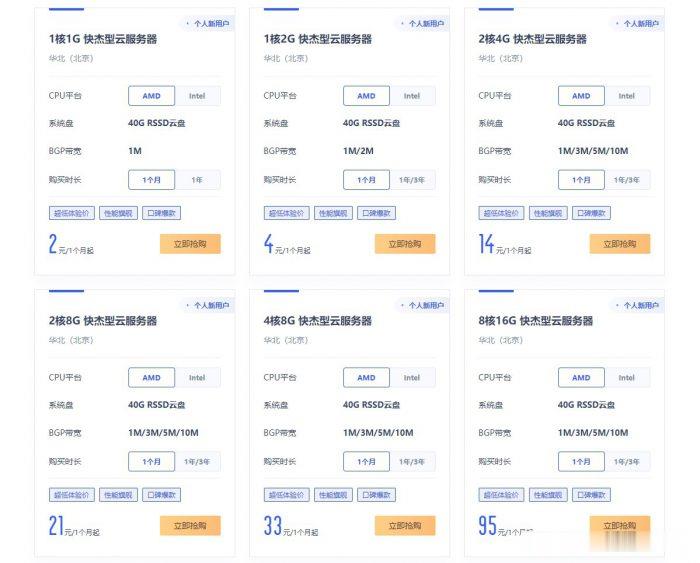
ucloud国内云服务器2元/月起;香港云服务器4元/首月;台湾云服务器3元/首月
ucloud云服务器怎么样?ucloud为了扩大云服务器市场份额,给出了超低价云服务器的促销活动,活动仍然是此前的Ucloud全球大促活动页面。目前,ucloud国内云服务器2元/月起;香港云服务器4元/首月;台湾云服务器3元/首月。相当于2-4元就可以试用国内、中国香港、中国台湾这三个地域的云服务器1个月了。ucloud全球大促仅限新用户,国内云服务器个人用户低至56元/年起,香港云服务器也仅8...

百纵科技云主机首月9元,站群1-8C同价,美国E52670*1,32G内存 50M 899元一月
百纵科技:美国高防服务器,洛杉矶C3机房 独家接入zenlayer清洗 带金盾硬防,CPU全系列E52670、E52680v3 DDR4内存 三星固态盘阵列!带宽接入了cn2/bgp线路,速度快,无需备案,非常适合国内外用户群体的外贸、搭建网站等用途。官方网站:https://www.baizon.cnC3机房,双程CN2线路,默认200G高防,3+1(高防IP),不限流量,季付送带宽美国洛杉矶C...

-
企业虚拟主机一般的企业应该用什么样的虚拟主机?海外主机为什么国外的主机和国内的有这么大的差别?代理主机什么叫做代理服务器?有什么用途?免费vps服务器请推荐一个免费的云服务器?成都虚拟空间五星网络隶属于成都冠一科技有限公司,虚拟空间购买了不到一个月不能访问2次,质量真差啊!成都虚拟空间成都有没有能玩ps主机游戏的网咖?香港虚拟主机香港虚拟主机多少钱一年呢?韩国虚拟主机香港和韩国的虚拟主机哪个比较好?虚拟主机控制面板虚拟主机管理面板与网站后台有什么区别?apache虚拟主机如何用Apache配置安全虚拟主机 - PHP进阶讨论