组件fastreport2.5
fastreport2.5 时间:2021-05-24 阅读:()
TPS24772TPS24771TPS24770ZHCSDK8–MARCH2015TPS2477x2.
5至至18V高高性性能能热热插插拔拔1特特性性3说说明明12.
5V至18V总线操作(30V绝对最大值)TPS2477x是一款针对2.
5V至18V系统的高性能模拟热插拔控制器.
TPS2477x精确且具有高度可编程可编程保护设置:保护设置,对设计故障隔离要求较高的高功率、高可用–电流限制:10mV时为±5%性系统很有帮助.
–快速跳变:20mV时为±10%可编程场效应管(FET)安全运行区域(SOA)保护该控制器还具有可编程电流限制、快速关断和故障定时可编程快速跳变的响应时间器功能,可在热短路等故障期间保护负载和电源.
可双定时器(浪涌/故障)调整快速关断阈值和响应时间,以确保快速响应实际故模拟电流监视器(25mV时为1%)障,同时避免误跳变.
该器件具有可编程的安全工作可编程欠压(UV)与过压(OV)区域(SOA)保护和浪涌定时器,可在所有条件下对金故障和电源正常状态标志属氧化物半导体场效应晶体管(MOSFET)加以保护.
4mm*4mm24引脚四方扁平无引线(QFN)封装TPS2477x将电源正常状态标志置为有效后,会在过流70=锁存,71=重试,72=快速锁存关闭事件期间作为断路器工作并运行故障定时器,但不会限制电流.
当故障定时器到期后,控制器会关断.
该控2应应用用制器具有两个独立定时器(浪涌/故障),用户可根据企业级存储系统需求定制保护功能.
企业级服务器最后,TPS2477x非常灵活,可帮助热插拔设计满足网络卡240VA要求,本数据表中给出了一个设计示例.
240VA应用器器件件信信息息(1)器器件件型型号号封封装装封封装装尺尺寸寸((标标称称值值))TPS24770TPS24771RGE(24)4.
00mmx4.
00mmTPS24772(1)要了解所有可用封装,请见数据表末尾的可订购产品附录.
4简简化化电电路路原原理理图图将将输输出出功功率率限限制制在在240VA,,20AILIM与与TPS2477x实实现现的的对对比比1AnIMPORTANTNOTICEattheendofthisdatasheetaddressesavailability,warranty,changes,useinsafety-criticalapplications,intellectualpropertymattersandotherimportantdisclaimers.
PRODUCTIONDATA.
EnglishDataSheet:SLVSCZ3TPS24772TPS24771TPS24770ZHCSDK8–MARCH2015www.
ti.
com.
cn目目录录9.
1Overview101特特性性.
19.
2FunctionalBlockDiagram102应应用用.
19.
3FeatureDescription.
113说说明明.
19.
4DeviceFunctionalModes.
164简简化化电电路路原原理理图图.
110ApplicationandImplementation.
175修修订订历历史史记记录录210.
1ApplicationInformation.
176DeviceComparisonTable.
310.
2TypicalApplication177PinConfigurationandFunctions.
311PowerSupplyRecommendations408Specifications.
412Layout.
408.
1AbsoluteMaximumRatings412.
1LayoutGuidelines408.
2ESDRatings412.
2LayoutExample428.
3RecommendedOperatingConditions.
513器器件件和和文文档档支支持持438.
4ThermalInformation513.
1相关链接.
438.
5ElectricalCharacteristics.
513.
2商标.
438.
6TimingRequirements713.
3静电放电警告.
438.
7TypicalCharacteristics.
813.
4术语表439DetailedDescription1014机机械械、、封封装装和和可可订订购购信信息息.
435修修订订历历史史记记录录日日期期修修订订版版本本注注释释2015年3月*最初发布.
2Copyright2015,TexasInstrumentsIncorporatedTPS24772TPS24771TPS24770www.
ti.
com.
cnZHCSDK8–MARCH20156DeviceComparisonTablePARTNUMBER(1)LATCH/RETRYOPTIONTPS24770LatchTPS24771Auto–RetryTPS24772FastLatchOff(1)Forthemostcurrentpackageandorderinginformation,seethePackageOptionAddendumattheendofthisdocument,orseetheTIwebsiteatwww.
ti.
com.
7PinConfigurationandFunctionsQFN24-PinwithThermalPadRGEPackageTopViewPinFunctionsPINTYPE(1)DESCRIPTIONNAMENO.
ENHS2IActive-highenableinputofHotSwap.
Logicinput.
Connectstoresistordivider.
FLTb4OActive-low,open-drainoutputindicatingvariousfaults.
FSTP16IFasttripprogrammingsetpinforHotSwap.
AresistorisconnectedfrompositiveterminalofRSNStoFSTP.
GND10–Ground.
HGATE18OGatedriveroutputforexternalHotSwapMOSFET.
IMON12I/OAnalogmonitorandcurrentlimitprogrampoint.
ConnectRIMONtoground.
IMONBUF13OVoltageoutputproportionaltotheloadcurrent(0V–3.
0V).
NC1,3,6,NCNoconnect.
Tietogroundorleavefloating.
20–24(1)I=Input;O=Output;P=Power,NC=NoConnectCopyright2015,TexasInstrumentsIncorporated3TPS24772TPS24771TPS24770ZHCSDK8–MARCH2015www.
ti.
com.
cnPinFunctions(continued)PINTYPE(1)DESCRIPTIONNAMENO.
OUTH19IOutputvoltagesensorformonitoringHotSwapMOSFET'spower.
ConnectstothesourceterminaloftheHotSwapNchannelMOSFET.
OV9IOvervoltagecomparatorinput.
Connectstoresistordivider.
HGATEispulledlowwhenOVexceedsthethreshold.
Connecttogroundwhennotused.
PGHS5OActive-high,open-drainpower-goodindicator.
PLIM11IPowerlimitprogrammingpin.
AresistorfromthispintoGNDsetsthemaximumpowerdissipationfortheHotSwapFET.
Connecta4.
99kΩresistortodisablepowerlimit.
SENM17ICurrent-sensinginputforthesenseresistor.
Directlyconnectstothenegativeterminalofthesenseresistor.
SET15ICurrent-limitprogrammingsetpinforHotSwap.
Aresistorisconnectedfrompositiveterminalofthesensingresistor.
TFLT8I/OFaulttimer,whichrunswhenthedeviceisinregularoperationandthereisanovercurrentcondition.
TINR7I/OInrushtimer,whichrunsduringtheinrushoperation(start-up)ifthepartisincurrentlimitorpowerlimit.
VDD14PPowerSupply8Specifications8.
1AbsoluteMaximumRatingsoveroperatingfree-airtemperaturerange(unlessotherwisenoted)(1)MINMAXUNITVDD,SET,FSTP,SENM,OUTH,ENHS,FLTb,PGHS,OV–0.
330VHGATEtoOUTH–0.
315VSETtoVDD–0.
30.
3VInputVoltageSENM,FSTPtoVDD–0.
60.
3VTINR,TFLT,PLIM,IMON–0.
33.
6VIMONBUF–0.
37VSinkCurrentFLTb,PGHS5mASourceCurrentIMON,IMONBUF5mAStoragetemperature,Tstg–65150°C(1)StressesbeyondthoselistedunderAbsoluteMaximumRatingsmaycausepermanentdamagetothedevice.
Thesearestressratingsonly,whichdonotimplyfunctionaloperationofthedeviceattheseoranyotherconditionsbeyondthoseindicatedunderRecommendedOperatingConditions.
Exposuretoabsolute-maximum-ratedconditionsforextendedperiodsmayaffectdevicereliability.
8.
2ESDRatingsVALUEUNITHuman-bodymodel(HBM),perANSI/ESDA/JEDECJS-001(2)±1500ElectrostaticV(ESD)(1)VdischargeCharged-devicemodel(CDM),perJEDECspecificationJESD22-C101(3)±500(1)Electrostaticdischarge(ESD)measuresdevicesensitivityandimmunitytodamagecausedbyassemblylineelectrostaticdischargesintothedevice.
(2)JEDECdocumentJEP155statesthat500-VHBMallowssafemanufacturingwithastandardESDcontrolprocess.
(3)JEDECdocumentJEP157statesthat250-VCDMallowssafemanufacturingwithastandardESDcontrolprocess.
4Copyright2015,TexasInstrumentsIncorporatedTPS24772TPS24771TPS24770www.
ti.
com.
cnZHCSDK8–MARCH20158.
3RecommendedOperatingConditionsoveroperatingfree-airtemperaturerange(unlessotherwisenoted)MINMAXUNITVDD,SENM,SET,FSTP2.
518InputvoltageVENHS,FLTb,PGHS,OUTH018SinkcurrentFLTb,PGHS02mASourcecurrentIMON01mAPLIM4.
99500kΩIMON16kΩExternalresistanceFSTP104000ΩSET10400Ωw/oRSTBL1070RIMON/RSETWithappropriateRSTBL(1)310withCHGATE>47nF(2)10200TINR,TFLT1nFHGATE,(2)01FExternalcapacitorIMON30pFIMONBUF100pFOperatingjunctiontemperature,TJ–40125°C(1)RefertoRSTBLRequirmentforRIMON/RSET101mV)HotSwaptimertimesout.
OverTemperatureShutDown(OTSD)Copyright2015,TexasInstrumentsIncorporated15TPS24772TPS24771TPS24770ZHCSDK8–MARCH2015www.
ti.
com.
cn9.
4DeviceFunctionalModes9.
4.
1HotSwapFunctionalModesThestatemachinefortheHotSwapsectionisshowninFigure17.
AfteraPOR/UVLOeventtheHotSwapenterstheInrushup.
OnceoperationaltheHotSwaphasthefollowingfunctionalmodes:InrushMode(INR):InthisstatetheHotSwapcontrollerisactivelyregulatingtheHGATEtomeetthecurrentlimitandpowerlimitsettings.
Theinrushtimerisrunningifthecontrollerisinpowerorcurrentlimiting.
Iftheinrushtimertimesoutthegatewillbepulleddown.
TheTPS24770andTPS24772willgotolatchedmodeandTPS24771willgointoretrymode.
RegularOperationMode(REG):InthismodeeverythingisoperatingproperlysoboththetimersaredischargedandtheHGATEishigh.
Ifthereisanovercurrentcondition(VSNS>VSNS,CL),thedevicewillgointofaultmode.
Ifthereisafasttripcondition(VSNS>VFSTP),thegatewillbepulleddownwitha1A/63spulse.
TheTPS24772willgotothelatchedstateandtheTPS24770andTPS24771willgobacktoinrushforaretry.
FaultMode(FLT):InthismodetheTPS2477xrunsthefaulttimer.
OncethetimerexpirestheTPS24770andTPS24772willgotolatchmodewhileTPS24771willgotoretrymode.
Iftheovercurrentconditionisremovedthecontrollerwillgobacktotheregularoperationmode.
LatchedMode(Latched):InthelatchedmodetheHGATEislow,thetimerisbeingdischarged,andtheFLTbisasserted.
IfthereisarisingedgeonENHSthepartwilldischargethetimersandgototheinrushmode.
RetryMode(Retry):Herethepartwillchargeanddischargetheinrushtimer64timesbeforeattemptinganotherretry.
Figure17.
HotSwapStateMachine16Copyright2015,TexasInstrumentsIncorporatedTPS24772TPS24771TPS24770www.
ti.
com.
cnZHCSDK8–MARCH201510ApplicationandImplementationNOTEInformationinthefollowingapplicationssectionsisnotpartoftheTIcomponentspecification,andTIdoesnotwarrantitsaccuracyorcompleteness.
TI'scustomersareresponsiblefordeterminingsuitabilityofcomponentsfortheirpurposes.
Customersshouldvalidateandtesttheirdesignimplementationtoconfirmsystemfunctionality.
10.
1ApplicationInformationTheTPS2477xisahighlyconfigurableHotSwapcontrollerthatcanbefine-tunedfortheapplicationrequirement.
WhendesigningaHotSwap3keyscenariosshouldbeconsidered:Start-up.
OutputofaHotSwapisshortedtogroundwhentheHotSwapison.
Thisisoftenreferredtoasa"Hot-Short".
Poweringupaboardwhentheoutputandgroundareshorted.
Thisisusuallycalleda"startintoshort".
AllofthesescenariosplacealotofstressontheHotSwapMOSFETandspecialcaremustbetakenwhendesigningtheHotSwapcircuittokeeptheMOSFETwithinitsSafeOperatingArea(SOA).
Notethatthecomponentselectioncanoftenbeiterativelyandit'srecommendedtousethepublicallyavailableexcelcalculatorstocrunchthenumbers.
SeetheTPS24770DesignCalculatorintheTools&SoftwarelinkontheProductfolder.
10.
2TypicalApplicationThreeapplicationexamplesareprovided.
Thefirstoneisfora100AHotSwapwith5,500Fofoutputcapacitancethatusesstandardpowerlimitedbasedstart-up.
Thentherearetwoexamplesofdesigningforthe240VAdesignrequirment.
OneusestheCSD16415Q5B,whichisanoldergenerationMOFSETwithgreatSOA.
ThesecondoneusestheCSD17573Q5B,whichhaslowerSOA,butismorecosteffective(pricevsRDSON).
10.
2.
112V,100A,5,500FAnalogHotSwapDesignThediagrambelowshowstheapplicationschematicforthisdesignexample.
Figure18.
ApplicationSchematicfor100AHotSwapCopyright2015,TexasInstrumentsIncorporated17TPS24772TPS24771TPS24770ZHCSDK8–MARCH2015www.
ti.
com.
cnTypicalApplication(continued)10.
2.
2DesignRequirementsTable1summarizesthedesignparametersthatmustbeknownbeforedesigningaHotSwapcircuit.
WhenchargingtheoutputcapacitorthroughtheHotSwapMOSFET,theFET'stotalenergydissipationequalsthetotalenergystoredintheoutputcapacitor(1/2CV2).
ThusboththeinputvoltageandoutputcapacitancewilldeterminethestressexperiencedbytheMOSFET.
Themaximumloadcurrentwilldrivethecurrentlimitandsenseresistorselection.
Inaddition,themaximumloadcurrent,maximumambienttemperature,andthethermalpropertiesofthePCB(RθCA)willdrivetheselectionoftheMOSFETRDSONandthenumberofMOSFETsused.
RθCAisastrongfunctionofthelayoutandtheamountofcopperthatisconnectedtothedrainoftheMOSFET.
AircoolingwillalsoreduceRθCA.
It'salsoimportanttoknowifthereareanytransientloadrequirements.
Finally,whethercurrentmonitoringisneededanditsaccuracyrequirementwilldrivetheselectionofRSNS,RIMON,andRSET.
Table1.
DesignRequirementsfora12V,100A,5500FHotSwapDesignDESIGNPARAMETEREXAMPLEVALUEInputvoltagerange11V–13VMaximumDCloadcurrent100AMaximumOutputCapacitanceoftheHotSwap5500FMaximumAmbientTemperature55°CMOSFETRθCA(functionoflayout)50°C/WTransientloadrequirement130Afor250msPass"Hot-Short"onOutputYesPassa"Startintoshort"YesIstheloadoffuntilPGassertedYesCanaHotBoardbepluggedinorPowerCycledNoICusedTPS24772AnalogCurrentMonitorUsedNo10.
2.
3DetailedDesignProcedure10.
2.
3.
1SelectRSNSandVSNS,CLSettingTPS2477xhasaprogrammableVSNS,CLwitharecommendedrangeof10mVto67.
5mV.
ItcanbeusedwithaVSNS,CLupto200mV,butthatrequiresaresistorbetweenSETandSENMtoensurestabilityofaninternalloop.
ThisisshowninFigure19.
RSTBLcanbecomputedusingtheequationbelow.
(10)ForhighpowerapplicationsalowerVSNS,CLleadstobetterefficiencyso20mVistargetedforthisdesign.
Targetingacurrentlimitof110Atoallowmarginfortheload,thesenseresistorcanbecalculatedasfollows:(11)Since0.
18mresistorsaren'tavailable,thecloseststandardresistorshouldbechosen.
Tohavebetterefficiency,three0.
5mresistorsareusedinparallel.
NexttheVSNS,CLshouldbecomputedbasedontheactualRSNSandthenusedtocomputeRSETandRIMON.
RSETischosentotarget250AofcurrentthroughSETandIMONpinsduringcurrentlimit.
(12)(13)ChoseRSETtoequal73.
2,whichistheclosestavailablestandardresistor.
NextobtainthecalculatedRIMON(RIMON,CLC)asfollows:(14)18Copyright2015,TexasInstrumentsIncorporatedTPS24772TPS24771TPS24770www.
ti.
com.
cnZHCSDK8–MARCH2015Choose2.
67kresistorforRIMON,whichistheclosestavailablestandardresistor.
Sinceaccuratecurrentmonitoringisnotneededa25122terminalsenseresistorcanbeused.
Finally,computetheactualcurrentlimit(ILIM,CL)andtheanalogcurrentmonitoringscalingfactorVIMON,GAIN(VIMONvsILOAD)(15)sp(16)Figure19.
AddingRSTBLforVSNS,CL>67.
5mV10.
2.
3.
2SelectingtheFastTripThresholdandFilteringTheTPS2477xallowstheusertoprogramthefasttripthreshold.
Whenthisthresholdisexceededthegateisquicklypulleddown(PLIMsotheHotSwapwillstartinpowerlimitandtransitionintocurrentlimit.
Inthatcasethemaximumstarttimecanbecomputedasfollows:(24)Notethattheabovestart-timeisbasedontypicalcurrentlimitandpowerlimitvalues.
Toensurethatthetimernevertimesoutduringstart-upitisrecommendedtosetthefaulttime(TINR)tobe1.
5xtstart,maxor6ms.
Thiswillaccountforthevariationinpowerlimit,timercurrent,andtimercapacitance.
NextthedesignershoulddecideifhavingequalTINRandTFLTisacceptable.
Notethattopasstheloadtransientthefaulttimerneedstobelongerthan200ms.
Iftheinrushtimeisthislong,itwillplacetoomuchstressontheMOSFETduringastartintoshort.
Forthisreason,it'sidealtohavetwoseparatetimers.
Toensureproperstartupandtopasstheloadtransientatargetinrushtime(TINR,TGT)of6msandatargetfaulttime(TFLT,TGT)of250msisused.
CINR,CLCandCFLT,CLCiscomputedasfollows:(25)sp(26)ThenextlargestavailableCINRischosenas47nFandthenextlargestavailableCFLTischosenas2.
2FNext,theactualTINRandTFLTcanbecomputedasshownbelow:OncetheCTMRischosentheactualprogrammedtimeoutcanbecomputedasfollows.
(27)sp(28)10.
2.
3.
6CheckMOSFETSOAOncethepowerlimitandfaulttimerarechosen,it'scriticaltocheckthattheFETwillstaywithinitsSOAduringalltestconditions.
ForthisdesignexampletheTPS24772isused,whichdoesnotretryduringahot-short.
Thustheworstconditionisastart-upintoashortcircuit.
InthiscasetheTPS24772willstartintoapowerlimitandregulateatthatpointfor6.
2ms(TINR).
BasedontheSOAoftheCSD16415Q5B,itcanhandle13V,15Afor10msanditcanhandle13V,100Afor1ms.
TheSOAfor6.
2mscanbeextrapolatedbyapproximatingSOAvstimeasapowerfunctionasshownbelow:(29)Copyright2015,TexasInstrumentsIncorporated21TPS24772TPS24771TPS24770ZHCSDK8–MARCH2015www.
ti.
com.
cnNotethattheSOAofaMOSFETisspecifiedatacasetemperatureof25°C,whilethecasetemperaturecanbehotterduringastartintoashort.
ItisimportanttounderstandthehottesttemperaturethataMOSFETcanbeduringastart-up(TC,MAX,START).
Ifaboardhasbeenoffforawhileandthenit'sturnedonTA,MAXisagoodestimateforTC,MAX,START.
However,ifaboardisonandthengetspowercycledorahotboardisunpluggedandpluggedbackinTC,MAXshouldbeusedforTC,MAX,START.
Thiswilldependonsystemrequirements.
Forthisdesignexampleit'sassumedthattheboardcanonlybepluggedincoldandTA,MAXisusedtoestimateTC,MAX,START.
(30)BasedonthiscalculationtheMOSFETcanhandle17A,13Vfor6.
2msat55°Celevatedcasetemperature,butisonlyrequiredtohandle9Aduringastartintoshort.
Thusthereisgoodmarginandthiswillbearobustdesign.
Ingeneral,itisrecommendedthattheMOSFETcanhandle1.
3xmorethanwhatisrequiredduringahot-short.
Thisprovidesmargintocoverthevarianceofthepowerlimitandfaulttime.
10.
2.
3.
7ChooseUnderVoltageandOverVoltageSettingsTheTPS2477xhascomparatorswith1.
35VthresholdontheENHS,ENOR,andOVpins.
AresistordividercanbeusedtosetUndervoltageandOvervoltagethresholdsforthebus.
Forthisdesignexample10Vand14Vwerechosenasthelimitstoallowsomemarginforthe11Vto13Vinputbus.
Oncetheselimitsareknown,RDIV2andRDIV3canbecomputedusingtheequationsbelow.
RDIV1wassetto49.
9k,whichkeepsthepowerconsumptionreasonablelowwithoutbeingtoosusceptibletoleakagecurrents.
(31)sp(32)sp(33)Chooseclosestavailableresistorsstandard1%resistors:RDIV2=2.
21kandRDIV3=5.
62k.
TheactualUnderVoltageandOverVoltagesettingscanbecomputedforthechosenresistorsasfollows:(34)sp(35)10.
2.
3.
8SelectingC1andCOUTItisrecommendedtoaddceramicbypasscapacitorstohelpstabilizethevoltagesontheinputandoutput.
SinceCINwillbechargeddirectlyonhot-plug,itsvalueshouldbekeptsmall.
0.
1Fisagoodtarget.
SinceCOUTdoesn'tgetchargedduringhot-plug,alargervaluesuchas1Fcouldbeused.
10.
2.
3.
9AddingCENHSWhentheENHSpinispulledbelowitsthresholdandraisedbackuptheICwillreset.
NotethatduringahotshorttheinputvoltagecaneasilydroopbelowtheUVthresholdandcycletheENHSpin.
FortheTPS24770andTPS24771ICsthiswillnotchangethebehavior.
However,whenusingtheTPS24772thecyclingoftheENHSwillresultintheICattemptingtorestart,whichisundesired(thisisthemainreasonwhysomeonewouldusetheTPS24772).
ToavoidthisbehavioracapacitorshouldbeaddedtotheENHStoprovidefiltering.
33nFwaschosenforthisexample.
22Copyright2015,TexasInstrumentsIncorporatedTPS24772TPS24771TPS24770www.
ti.
com.
cnZHCSDK8–MARCH201510.
2.
3.
10SelectingD1andD2DuringhotplugandhotshorteventstherecouldbesignificanttransientsontheinputandoutputoftheHotSwapthatcouldcauseoperationoutsideoftheICspecifications.
ToensurereliableoperationaTVSontheinputandaSchottkeydiodeontheoutputarerecommended.
InthisexampleaSMDJ14AandMBRS330T3Gareused.
10.
2.
3.
11CheckingStabilityFormostapplications,theTPS2477xisstablewithoutanyadditionalcomponents.
HoweverinsomecasesadditionalCGS,EXTisrequiredasshowninthefollowingfiguretohelpstabilizethecurrentandpowerlimitloop.
Typicallythisisforlowcurrentlimitsandlowsensevoltages.
Itiseasytocheckwhethertheseextracomponentsareneededusingtheequationsbelow.
Notethatthetransconductance(alsoreferredtoasgmandgfs)oftheFETwillvarybasedonthecurrentandthusgm'isusedintheequationsasanormalizingparameter.
TheCSD16415Q5Bhasagmof168siemensat40AofIDS,resultingingm'of26.
56.
Forthisexample,CGS,MIN(perFET)wascomputedtobe0.
25nF,whiletheCISSoftheCSD16415Q5Bis3.
15nFprovidingplentyofmarginforthedesign.
Ingeneralitisrecommendedtohavea2xmarginfromthetypicalCISSandCGS,MINtoaccountforanyvariationthattheFETwouldhave.
IftheCISSoftheMOSFETisn'tlargeenoughanexternalRCshouldbeaddedasshowninthefigurebelow.
(36)(37)(38)Figure20.
AddingCGS,EXTtoEnsureStability10.
2.
3.
12ComputeTolerancesAfterfinishingadesignitisoftendesiredtoknowthevariationsofeachsetting.
Oftentimestherearemultipleerrorsourcesandtherearetwocommonwaystoanalyzethecircuit.
Oneisworstcase,whichaddsalloftheerrorsourcesandtheotheroneisrootsumsquare(RSS),whichislessconservative.
Whenerrorsourcesareindependent,usingtheRSSmethodprovidesamorestatisticallyaccurateviewofthetolerances.
Thismethodisusedinthissection.
Notethattheerrorcalculationsarequitelongandtediousandit'srecommendedtouseTI'sexceltools,whichsupportbothworstcaseandRSSanalysis.
Forthisexamplethebelowtolerancesareassumed.
Thefollowingtableliststheassumptionsforthecomponenttolerances.
Notethatthesenseresistoritselfis1%accurate,butmultipletwoterminal2512resistorsareusedsoadditionalerrorisintroducedfromsolderresistanceandlayoutlimitationsofparallelingresistors.
Forthisexample3%isassumedasthetotalerrorofthesensingnetwork.
Copyright2015,TexasInstrumentsIncorporated23TPS24772TPS24771TPS24770ZHCSDK8–MARCH2015www.
ti.
com.
cnTable2.
ComponentTolerancesCOMPONENTSTOLERANCERIMONandRSET1%RSNS(IncludingLayout+Soldering)3%RDIV1,RDIV2,RDIV3,RPLIM,RFST1%CINR,CFLT10%First,thetoleranceofthecurrentmonitoringandcurrentlimitiscomputed.
Thereare5errorsourcingcontributingtothecurrentmonitoringaccuracyontheIMONpin:toleranceofRSET(ERSET),toleranceofRIMON(ERIMON),toleranceofRSNS(ERSNS),theICgainerror(ERGAIN),andtheICoffseterror(EROS).
Alloftheseerrorsarein%withtheexceptionoftheoffseterror.
Togetapercenterrorduetotheoffseterror(EROS%)simplydividetheoffsetbythesensevoltage.
FortheTPS2477x,ERGAINis0.
4%,andEROSis150V.
Basedonthesevaluesthefullscale(IFS,ERR,IMON)currentmonitoringaccuracyattheImonpincanbecomputedwiththefollowingequations.
(39)NotethattheTPS2477xdetectsthecurrentlimitwhentheIMONpinexceeds675mV.
ThusthecurrentlimiterrorILIM,ERisacombinationoftheIFS,ERR,IMONandthecurrentlimiterrorattheIMONpin(ILIM,ERR,IMON).
The675mVthresholdvariesupto15mVsoILIM,ERR,IMONis2.
3%andthecurrentlimiterrorcanbecomputedasfollows:(40)Nextthepowerlimiterroriscomputed.
Thiserrorismadeupofthreesources:theerrorfromexternalcomponents(ERCOMP),theerrorwhentranslatingthesensevoltagetoIMON(IPL,ERR,IMON),andtheerrorofthepowerlimitengineatIMON(ERIMON,PL).
BothERSNSandERIMON,PLareafunctionoftheoperatingpointofthepowerlimitengine.
NotethatthiserrorisgreatestatlargestVDS,sinceVSNS,PLissmallest(refertoFigure12).
ForthisexampleVDSislargestwhenVIN=13V(maximumVIN)andVOUT=0Vandtheerroriscomputedatthisoperatingpoint.
Thesensevoltage(VSNS)andthevoltageattheIMONpin(VIMON)shouldbecomputedforthisoperatingpointusingtheequationsbelow:(41)sp(42)TheIPL,ERR,IMONcanbecomputedsimilarlytoIFS,ERR,IMONusingtheequationbelow.
sp(43)ThetoleranceofthepowerlimitengineisspecifiedatthreeVIMONpointsinthedatasheet:135mV(±20.
3mV),67.
5mV(±10.
1mV),and27mV(±8.
1mV).
Togetthe%errorattherealoperatingpoint,theabsoluteerrorshouldbeextrapolatedanddividedbyVIMONasshownintheequationbelow.
ThisisgraphicallydepictedinFigure23.
(44)24Copyright2015,TexasInstrumentsIncorporatedTPS24772TPS24771TPS24770www.
ti.
com.
cnZHCSDK8–MARCH2015Figure21.
ExtrapolatingPowerLimitErrorOnceERIMON,PLandIPL,ERR,IMONareknownthetotalpowerlimiterror(PLERR,TOT)canbecomputedusingtheequationbelow.
Thecomponenterror(3.
5%)comesfromRSNS(3%),RPLIM(1%),RSET(1%),andRIMON(1%).
(45)Aftercomputingthefasttripvoltagethresholdtobe24.
9mV(100A*249),thefasttripthresholderrorresultingfromtheIC(FSTERR,IC)canbecomputedusingasimilarextrapolationmethodasusedforpowerlimit.
ThecomponenterrorofRSNSandRFSTshouldbeaddedtoobtainthetotalfasttriperror(FSTERR,TOT).
Bothequationsareshownbelow.
(46)sp(47)TheICerroroftheUV/OVthresholdisalways3.
7%(0.
05V/1.
35V).
Assumingthatallresistorshavea1%errorthecomponenterroris1.
41%(2resistors).
WhenusingtheRSSmethodthetotalerroris4%.
Forthetimererror,theICcontributes22%and10%comesfromthecomponent.
WhenusingtheRSSmethodthetotalerrorbecomes24.
2%.
Thetablebelowsummarizesthefinaltolerancesofthedesign:Table3.
DesignTolerancesSETTINGSACCURACYCurrentLimit4.
1%FastTrip9.
4%PowerLimit20.
3%TFLT,TINR24.
2%UV/OV4.
0%Copyright2015,TexasInstrumentsIncorporated25TPS24772TPS24771TPS24770ZHCSDK8–MARCH2015www.
ti.
com.
cn10.
2.
4ApplicationCurvesFigure22.
Startup(COUT=5500F)Figure23.
UndervoltageandOvervoltageFigure24.
StartUpwithOutputShortedtoGNDFigure25.
LoadStep100Ato120AFigure26.
HotShortonOutputwithFullLoadFigure27.
HotShortonOutputwithFullLoad(zoomedout)(zoomedin)26Copyright2015,TexasInstrumentsIncorporatedTPS24772TPS24771TPS24770www.
ti.
com.
cnZHCSDK8–MARCH2015Figure28.
HotShortonOutputwithNoLoad(zoomedout)Figure29.
HotShortonOutputwithNoLoad(zoomedin)10.
2.
5240VAApplicationUsingCSD16415Q5BThediagrambelowshowstheapplicationschematicforthisdesignexample.
SeetheTPS24770DesignCalculatortohelpwiththesecalculations.
Figure30.
ApplicationSchematicfor240VADesignwithCSD16415Q5B10.
2.
5.
1DesignRequirementsThefollowingtablesummarizestherequirementsforthisdesign.
Notethattheoutputpowercannotexceed240Wformorethan250ms.
Copyright2015,TexasInstrumentsIncorporated27TPS24772TPS24771TPS24770ZHCSDK8–MARCH2015www.
ti.
com.
cnTable4.
DesignRequirementsfora240VADesignusingCSD16415Q5BDESIGNPARAMETEREXAMPLEVALUEInputvoltagerange10.
8V–13.
2VOutputPowerLimit(VAlimiting)240WMaximumOutputCapacitanceoftheHotSwap2500uFMaximumAmbientTemperature55°CMOSFETRθCA(functionoflayout)35°C/WTransientloadrequirementPOUTisallowedtosurpass240Wfor<250msPass"Hot-Short"onOutputYesPassa"Startintoshort"YesIstheloadoffuntilPGassertedYesICusedTPS24772AnalogCurrentMonitorUsedNoMOSFETCSD16415Q5BCanaHotBoardbepluggedinorPowerCycledYes10.
2.
5.
2TheoryofOperationsBeforegoingintothedetailsofthedesignit'simportanttounderstandtheimpactthatRPOWhasonthecircuit.
RefertoFigure31forthisdiscussion.
Figure31.
ImpactofRPOWResistorNotethattheTPS2477xdetectsovercurrentconditionswhenVIMONreaches675mV,whichoccurswhenthereissufficientcurrent(iIMON)flowingthroughRIMON.
AlsonotethatiIMONisasumofiSETandiPOW.
IfiIMON,CL,iSET,CL,andiPOW,CLcorrespondtothesesamecurrentwhenVIMONreaches675mVandTPS2477xdetectscurrentlimit,thefollowingequationscanbewritten.
(48)(49)28Copyright2015,TexasInstrumentsIncorporatedTPS24772TPS24771TPS24770www.
ti.
com.
cnZHCSDK8–MARCH2015AlsonotethattheamplifierensuresthatSETandSENMareequalandthusILIMcanbederivedasfollows:(50)(51)Examiningtheequationabove,itcanbeseenthatILIMreducesasVINbecomeslarger.
Notethattheultimategoalistolimitoutputpower.
However,whentheFETison,VINisveryclosetoVOUTandtheycanbeassumedtobeequal.
ThefigurebelowcomparestheidealILIMvsVOUT(ILIM=240W/VOUT)profiletothatoftheRPOWimplementationshownhere.
Theerrorislargewhentheoutputvoltageisfarfrom12V,buttheperformanceisquitegoodnear12V.
Thenextfigureshowstheeffectiveoutputpowerlimitforoutputvoltagesfrom10Vto14V.
Itcanbeseenthattheresultsarequitegoodandmuchbetterthanusingasimple20Acurrentlimit,withouttheRPOWresistortocompensateforVINvariation.
Figure32.
CurrentLimit(withRPOW)vsOutputVoltageFigure33.
OutputPowerLimitingusingRPOWvsStandardILIM10.
2.
5.
3DesignProcedure10.
2.
5.
3.
1SelectVSNS,CL,RSNS,andRSETSettingForthisexample,VSNS,CLof10mVwasselectedtooptimizeefficiency.
ThenRSNScanbecomputedto0.
5m.
ThereissomeflexibilityinpickingtheRSETvalue.
Inthiscasetargeting100AforISET,CL,RSETiscomputedtobe100asshowninthefollowingequation.
(52)10.
2.
5.
3.
1.
1SelectRPOWandRIMONRPOWcontrolstheslopeoftheILIMvsVINcurveandthustheidealslopeshouldbefoundfirstbeforeselectingRPOW.
Thiscanbedonebytakingthederivativeoftheidealcurrentlimit(ILIM,IDEAL)vsVINcurveandevaluatingitat12V.
Thisisfoundtobe–1.
667A/Vasshownintheequationsbelow.
Nextthederivativeofequation51istakentoisolatethetermsthatinfluencetheslopeofILIMvsVINcurve.
SinceRSETandRSNShavealreadybeenselected,RPOWremainstheonlyparameterthatcanbevaried.
Thus,RPOWiscomputedusingthelastequationbelow.
(53)(54)Copyright2015,TexasInstrumentsIncorporated29TPS24772TPS24771TPS24770ZHCSDK8–MARCH2015www.
ti.
com.
cn(55)TheclosestavailablestandardresistorischosenforRPOW,whichis121k.
NextRIMONshouldbechosentoensurethattheoutputpowerlimitis240Wat12V,whichisthetypicaloperatingpoint.
RIMONiscomputedtobe3.
49kandtheclosestavailablestandardresistorof3.
48kischosen.
(56)sp(57)10.
2.
5.
3.
1.
2SelectingtheHotSwapFET(s)ItiscriticaltoselectthecorrectMOSFETforaHotSwapdesign.
Thedevicemustmeetthefollowingrequirements:TheVDSratingshouldbesufficienttohandlethemaximumsystemvoltagealongwithanyringingcausedbytransients.
Formost12Vsystemsa25Vor30VFETisagoodchoice.
TheSOAoftheFETshouldbesufficienttohandleallusagecases:start-up,hot-short,startintoshort.
RDSONshouldbesufficientlylowtomaintainthejunctionandcasetemperaturebelowthemaximumratingoftheFET.
Infact,itisrecommendedtokeepthesteadystateFETtemperaturebelow125°Ctoallowmargintohandletransients.
Maximumcontinuouscurrentratingshouldbeabovethemaximumloadcurrentandthepulseddraincurrentmustbegreaterthanthecurrentthresholdofthecircuitbreaker.
MostMOSFETsthatpassthefirstthreerequirementswillalsopassthesetwo.
AVGSratingof+16Visrequired,becausetheTPS2477xcanpullupthegateashighas15.
5Vabovesource.
ForthisdesigntheCSD16415Q5BwasselectedforitslowRDSONandsuperiorSOA.
AfterselectingtheMOSFET,themaximumsteadystatecasetemperaturecanbecomputedasfollows:(58)IntheequationabovenisthenumberofFETsusedinparallel.
NotethattheRDSONisastrongfunctionofjunctiontemperature,whichformostMOSFETSwillbeveryclosetothecasetemperature.
AfewiterationsoftheaboveequationsmaybenecessarytoconvergeonthefinalRDSONandTC,MAXvalue.
AccordingtotheCSD16415Q5Bdatasheet,itsRDSONisabout1.
2xgreaterat75°Ccomparedtoroomtemperature.
.
TheequationbelowusesthisRDSONvaluetocomputetheTC,MAX.
NotethatthecomputedTC,MAXisclosetothejunctiontemperatureassumedforRDSON.
Thusnofurtheriterationsarenecessary.
(59)10.
2.
5.
3.
1.
3KeepingMOSFETwithinSOADuringNormalStart-upNext,thedesignermustensurethattheMOSFETwillstaywithinSOAduringstart-upandastart-upintoshort.
NotethattheTPS24772(fastlatchoff)isusedforthisdesignsotheMOSFETstressduringahotshortisminimal.
SinceRPOWbiasestheIMONpin,itinterfereswithFETpowerlimitingandit'srecommendedtodisableFETpowerlimitingitbyselectinga4.
99kresistorforRPOW.
30Copyright2015,TexasInstrumentsIncorporatedTPS24772TPS24771TPS24770www.
ti.
com.
cnZHCSDK8–MARCH2015TheinrushcurrentcanbelimitedbyaddingacapacitorfromHGATEtoGND(CDVDT)asshownintheapplicationdiagram.
ThiscapacitorlimitstheslewrateofHGATEatstart-up,whichwillinturnlimittheslewrateofVOUT.
AssumingthattheloadisoffuntilPGHSisasserted,alloftheinrushcurrentwouldbegoingintoCOUTandbeinverselyproportionaltotheslewrateofVOUT.
Refertotheapplicationplotsforastart-upwaveform.
Inaddition,a1kresistorisplacedinserieswithCDVDTtoensurethatCDVDTdoesn'tslowdowntheshortcircuitresponseoftheHotSwap.
Forthisexample,a100nFcapacitorwasusedforCDVDT.
Thisresultsinaninrushcurrent(IINR)of1.
375A,totalinrushtime(tINR)of24.
5,andpeakFETpowerdissipation(PFET,PEAK)of18.
7Wasshowninequationsbelow.
Thisassumesmaximuminputvoltageof13.
2V(60)sp(61)sp(62)Next,it'simportationtocheckthattheMOSFETcanhandlethisstresslevel.
NotethatthepowerdissipationoftheMOSFETwillstartatPINR,MAXandwillreducetozeroastheVDSdropacrosstheMOSFETreduces.
TheeffectivestressontheMOSFETcanbeapproximatedtobePINR,MAXfortINR/2,whichistheequivalentamountofenergy.
Forthisexample,theFETstressis18.
7Wfor12.
3ms.
LookingattheSOAcurveoftheCSD16415Q5B,atVDSof13.
2Vitcanhandle~15Afor10msor~4Afor100ms.
Usingthesamemethodasthepreviousdesignexample,itcanbecomputedthattheMOSFETcanhandle13.
4Afor12.
3mswhenVDS=13.
2V.
TheSOAofaMOSFETisspecifiedatacasetemperatureof25°C,whiletherealcasetemperaturecanbehotterduringastartintoashort.
ItisimportanttounderstandthehottesttemperaturethataMOSFETcanbeduringastart-up(TC,MAX,START).
Ifaboardhasbeenoffforawhileandthenit'sturnedon,TA,MAXisagoodestimateforTC,MAX,START.
However,ifaboardisonandthengetspowercycledorgetsunpluggedandpluggedbackin,TC,MAXshouldbeusedforTC,MAX,START.
Thiswilldependonsystemrequirements.
Forthisdesignexample,itisassumedthatahotboardcanbepowercycledorhotpluggedandthusTC,MAXisusedtoestimateTC,MAX,START.
(63)BasedonthiscalculationtheMOSFETcanhandle8.
4A,13.
2Vfor12.
3msat72°Celevatedcasetemperature,butisonlyrequiredtohandle1.
375A.
Thusthereisgoodmarginandthiswillbearobustdesign.
Ingenerala1.
3xmarginisrecommendedtocoverforvariations.
Next,thestartintoshortcaseisconsidered.
SincetheMOSFETpowerlimitisdisabled,thecurrentthroughtheMOSFETwillreach20Abeforethepartstartstoregulateandrunstheinrushtimer.
InordertominimizeFETstress,ashortinrushtimerischosen(1nFofCINR).
Unfortunately,whenaveryshorttimerisusedandthereisadv/dtcapacitor,theFETstresscannotbesimplyestimatedbyTINR.
Inthefollowingfigure,itisclearthattheFEThasbothvoltageandsignificantcurrentacrossitforlongerthanjustTINR.
ThisoccursbecauseTINRisonlyactivatedwhenIINreachesthecurrentlimitthreshold,whichdoesn'thappenimmediatelyduetotheslowdv/dtonthegateandthelimitedtransconductanceoftheFET.
Thecurrentisnotasquarepulse,whichmakesithardtocomparetheFETstresstotheSOAcurves.
Thusthestressshowninthefollowingfigureneedstobeconvertedtoanequivalentsquarepulse.
Forthisexample,theequivalentpulsewasassumedtobe20Afor1ms.
TheMOSFETcanhandle100A,13.
2Vfor1ms,whichcanbederatedto62Awhenaccountingforelevatedcasetemperature.
Thisprovidesplentyofmarginandensuresarobustdesign.
Copyright2015,TexasInstrumentsIncorporated31TPS24772TPS24771TPS24770ZHCSDK8–MARCH2015www.
ti.
com.
cn(64)Figure34.
Start-upIntoShort10.
2.
5.
3.
1.
4ChooseFaultTimerTopasstheloadtransient,atargetfaulttime(TFLT,TGT)of250msisused.
CFLT,CLCiscomputedasfollows:sp(65)ThenextlargestavailableCFLTischosenas2.
2F,whichresultsinaTFLTof290msasshownbelow.
(66)10.
2.
5.
3.
1.
5ChooseUnderVoltageandOverVoltageSettingsForthisdesignexample10Vand14Vwerechosenasthelimitstoallowsomemarginforthe10.
8Vto13.
2Vinputbus.
Theseareidenticaltothepreviousdesignexample.
SeeChooseUnderVoltageandOverVoltageSettingssectionforprogrammingthesethresholds.
10.
2.
5.
3.
1.
6SelectingCINandCOUTItisrecommendedtoaddceramicbypasscapacitorstohelpstabilizethevoltagesontheinputandoutput.
SinceCINwillbechargeddirectlyonhot-plug,it'svalueshouldbekeptsmall.
0.
1Fisagoodtarget.
SinceCOUTdoesn'tgetchargedduringhot-plug,alargervaluesuchas1Fcouldbeused.
10.
2.
5.
3.
1.
7SelectingD1andD2DuringhotplugandhotshorteventstherecouldbesignificanttransientsontheinputandoutputoftheHotSwapthatcouldcauseoperationoutsideoftheICspecifications.
ToensurereliableoperationaTVSontheinputandaSchottkeydiodeontheoutputarerecommended.
InthisexampleaSMDJ14AandMBRS330T3Gareused.
32Copyright2015,TexasInstrumentsIncorporatedTPS24772TPS24771TPS24770www.
ti.
com.
cnZHCSDK8–MARCH201510.
2.
5.
3.
1.
8AddingCENHSWhentheENHSpulledbelowitsthresholdandraisedbackuptheICwillreset.
NotethatduringahotshorttheinputvoltagecaneasilydroopbelowtheUVthresholdandcycletheENHSpin.
FortheTPS24770andTPS24771ICsthiswillnotchangethebehavior.
However,whenusingtheTPS24772thecyclingoftheENHSwillresultintheICattemptingtorestart,whichisundesired(thisisthemainreasonwhysomeonewouldusetheTPS24772).
ToavoidthisbehavioracapacitorshouldbeaddedtotheENHStoprovidefiltering.
33nFwaschosenforthisexample.
10.
2.
5.
3.
1.
9StabilityConsiderationsSincethereisa100nFCDVDTattachedtoHGATE,thissignificantlyincreasestheeffectivecapacitanceofHGATEandguaranteesstabilityforthisapplication.
10.
2.
5.
4ApplicationCurvesFigure35.
NoLoadthenHotShort(ZoomedOut)Figure36.
FullLoadthenHotShort(ZoomedIn)Figure37.
OvercurrentFigure38.
StartUpintoShortCopyright2015,TexasInstrumentsIncorporated33TPS24772TPS24771TPS24770ZHCSDK8–MARCH2015www.
ti.
com.
cnFigure39.
Startup(COUT=2500F)Figure40.
StartupshowingPGHSandFLTb(COUT=2500F)Figure41.
UnderVoltageandOverVoltagewithVINRising34Copyright2015,TexasInstrumentsIncorporatedTPS24772TPS24771TPS24770www.
ti.
com.
cnZHCSDK8–MARCH201510.
2.
6240VAApplicationUsingCSD17573Q5BThisdesignexamplehasidenticalrequirementstothepreviousone,buttheCSD17573Q5BisusedinsteadoftheCSD16415Q5B.
TheCSD17573Q5BischeaperandoffersbetterRDSON,butitsSOAisnotasgood.
ThusitwasnecessarytoaddQ2andRSET2toreducethestressduringastartupintoashortcircuit.
GiventhatQ2isasmallsignalPFETthatischeap,theoverallBOMcostofthissolutionshouldbecheaperthanthepreviousone.
SeetheTPS24770DesignCalculatortohelpwiththesecalculations.
Figure42.
240VADesignUsingCSD17573Q5BCopyright2015,TexasInstrumentsIncorporated35TPS24772TPS24771TPS24770ZHCSDK8–MARCH2015www.
ti.
com.
cn10.
2.
6.
1DesignRequirementsThefollowingtablesummarizestherequirementsforthisdesign.
Table5.
DesignRequirementsforthe240VADesignUsingCSD17573Q5BDESIGNPARAMETEREXAMPLEVALUEInputvoltagerange10.
8V–13.
2VOutputPowerLimit(VAlimiting)240WMaximumOutputCapacitanceoftheHotSwap2500FMaximumAmbientTemperature55°CMOSFETRθCA(functionoflayout)35°C/WTransientloadrequirementPOUTisallowedtosurpass240Wfor<250msPass"Hot-Short"onOutputYesPassa"Startintoshort"YesIstheloadoffuntilPGisassertedYesICusedTPS24772AnalogCurrentMonitorUsedNoMOSFETCSD17573Q5BCanaHotBoardbepluggedinorPowerCycledYes10.
2.
6.
1.
1ChoosingC1,COUT,CFLT,CENHS,D1,D2,RSET,RPOW,RIMON,RSNS,CDVDT,RPLIM,andUV/OVThresholdsThesecomponentsandsettingsarechoseninthesamefashionasthepreviousdesignexample.
See240VAApplicationUsingCSD16415Q5B.
10.
2.
6.
1.
2SelectingtheHotSwapFET(s)ItiscriticaltoselectthecorrectMOSFETforaHotSwapdesign.
Thedevicemustmeetthefollowingrequirements:TheVDSratingshouldbesufficienttohandlethemaximumsystemvoltagealongwithanyringingcausedbytransients.
Formost12Vsystemsa25Vor30VFETisagoodchoice.
TheSOAoftheFETshouldbesufficienttohandleallusagecases:start-up,hot-short,startintoshort.
RDSONshouldbesufficientlylowtomaintainthejunctionandcasetemperaturebelowthemaximumratingoftheFET.
Infact,itisrecommendedtokeepthesteadystateFETtemperaturebelow125°Ctoallowmargintohandletransients.
Maximumcontinuouscurrentratingshouldbeabovethemaximumloadcurrentandthepulseddraincurrentmustbegreaterthanthecurrentthresholdofthecircuitbreaker.
MostMOSFETsthatpassthefirstthreerequirementswillalsopassthesetwo.
AVGSratingof+16Visrequired,becausetheTPS2477xcanpullupthegateashighas15.
5Vabovesource.
ForthisdesigntheCSD17573Q5BwasselectedforitslowRDSONandgreatcostpoint.
AfterselectingtheMOSFET,themaximumsteadystatecasetemperaturecanbecomputedasfollows:(67)IntheequationabovenisthenumberofFETsusedinparallel.
NotethattheRDSONisastrongfunctionofjunctiontemperature,whichformostMOSFETSwillbeveryclosetothecasetemperature.
AfewiterationsoftheaboveequationsmaybenecessarytoconvergeonthefinalRDSONandTC,MAXvalue.
AccordingtotheCSD17573Q5Bdatasheet,itsRDSONisabout1.
2xgreaterat65°Ccomparedtoroomtemperature.
TheequationbelowusesthisRDSONvaluetocomputetheTC,MAX.
NotethatthecomputedTC,MAXisclosetothejunctiontemperatureassumedforRDSON.
Thusnofurtheriterationsarenecessary.
(68)36Copyright2015,TexasInstrumentsIncorporatedTPS24772TPS24771TPS24770www.
ti.
com.
cnZHCSDK8–MARCH201510.
2.
6.
1.
3KeepingtheMOSFETwithinSOAAsinthepreviousexample,itisimportanttoensurethattheMOSFETstayswithinitsSOAduringbothregularstart-upandstart-upintoshort.
Firstconsidertheregularstart-up.
ThesameCDVDTisusedasthelastexamplesotheFETisrequiredtohandle18.
2W(or1.
38Aand13.
2V)for12.
3ms.
BasedontheSOAcurveoftheCSD17573Q55B,atVDSof13.
2Vitcanhandle4.
5Afor10msor2Afor100ms.
Usingthesamemethodasthepreviousdesignexample,itcanbeinferredthattheMOSFETcanhandle4.
2Afor12.
3mswhenVDS=13.
2V.
TheSOAofaMOSFETisspecifiedatacasetemperatureof25°C,whilethecasetemperaturecanbehotterduringastartintoashort.
ItisimportanttounderstandthehottesttemperaturethataMOSFETcanbeduringastart-up(TC,MAX,START).
Ifaboardhasbeenoffforawhileandthenit'sturnedonTA,MAXisagoodestimateforTC,MAX,START.
However,ifaboardisonandthengetspowercycledTC,MAXshouldbeusedforTC,MAX,START.
Thiswilldependonsystemrequirements.
Forthisdesignexample,it'sassumedthatahotboardcanbepowercycledorhotpluggedandTC,MAXisusedtoestimateTC,MAX,START.
(69)BasedonthiscalculationtheMOSFETcanhandle2.
7A,13.
2Vfor12.
3msat69°Celevatedcasetemperature,butisonlyrequiredtohandle1.
38A.
Thusthereissufficientmargintomakethisarobustdesign.
Againa1.
3xmarginisrecommendedtocoverforvariations.
Next,considerthestartintoshortcondition.
SimilartothepreviousdesigntheMOSFETwouldneedtohandle20Aand13.
2Vfor~1ms.
CheckingtheSOAcurveoftheCSD17573Q5B,itcanonlyhandle10Aand13.
2Vfor1ms,soit'sSOAisclearlynotsufficient.
ThisiswhereQ2andRSET2comein.
Theyservetoreducethecurrentlimitduringstartingup(ILIM,START)whiletheVDSoftheHotSwapMOSFETisaboveVTofQ2(1Vto2V).
TheratioofILIMtoILIM,START,denotedasIRATIO,isafunctionofRSETandRSET2asshownbelow.
Forthisexamplearatioof0.
2(ILIM,START=4A)wastargetedtoreduceMOSFETstress,keepthecurrentlimitaboveIINR,andensuresufficientsignalonVSNStokeeptheerrorreasonable.
OnceIRATIOischosen,RSET2iscomputedtobe25asshownbelow.
(70)(71)Thestart-upintoshort(withRSET2andQ2)isshowninFigure43below.
Theequivalentpowerpulseisnow4Afor~0.
5ms.
TheMOSFETcanhandle10A,13.
2Vfor1ms,whichcanbederatedto6.
5Awhenaccountingforelevatedcasetemperature.
SincetheMOSFETisonlyrequiredtohandle4Afor0.
5msthereisplentyofmargininthedesign.
(72)Copyright2015,TexasInstrumentsIncorporated37TPS24772TPS24771TPS24770ZHCSDK8–MARCH2015www.
ti.
com.
cnFigure43.
Start-upIntoShort(withRSETandQ2)10.
2.
6.
2Q2SelectionThereisalotofflexibilitywhenselectingQ2.
AnyPMOSwitha±20VVGSratingand20VofVDSratingissufficient.
ForthisexampleIRLML5203PbFwasused.
Notethatthe100kseriesresistoralongwiththeCISSofQ2(~500pF)forafilterwitha50stimeconstant.
ThisprotectsQ2incasethereishighfrequencyringingonVINthatcausesVIN–VOUTtoexceed20V.
Thiswillusuallyhappenedduringhot-plugorhot-short.
10.
2.
6.
3ApplicationCurvesFigure44.
FullLoadthenHotShort(ZoomedOut)Figure45.
FullLoadthenHotShort(ZoomedIn)38Copyright2015,TexasInstrumentsIncorporatedTPS24772TPS24771TPS24770www.
ti.
com.
cnZHCSDK8–MARCH2015Figure46.
OverCurrentFigure47.
StartUpIntoShortFigure48.
Startup(COUT=2500F)Figure49.
StartupshowingPGHSandFLTb(COUT=2500F)Figure50.
Copyright2015,TexasInstrumentsIncorporated39TPS24772TPS24771TPS24770ZHCSDK8–MARCH2015www.
ti.
com.
cn11PowerSupplyRecommendationsIngeneral,operationisbestwhentheinputsupplyisn'tnoisyanddoesn'thavesignificanttransients.
Fornoisierenvironmentsfilteringoninput,output,andfasttripshouldbeadjustedtoavoidnuisancetrips.
12Layout12.
1LayoutGuidelinesWhendoingthelayoutoftheTPS2477xthefollowingareconsideredbestpractice.
EnsureproperKelvinSenseofRSNS.
KeepthefilteringcapacitorCFSTPasclosetotheICaspossible.
PlaceaShottkydiodeandaceramicbypasscapacitorclosetothesourceoftheHotSwapMOSFETDonotconnectVDDtotheKelvinSensetraceforSETandFSTPNotethatspecialcaremustbetakenwhenplacingthebypasscapacitorfortheVDDpin.
DuringHotShorts,thereisaverylargedv/dtoninputvoltageduringtheMOSFETturnoff.
IfthebypasscapacitorisplacedrightnexttothepinandthetracefromRSNStothepinislong,anLCfilterisformed.
AsaresultalargedifferentialvoltagecandevelopbetweenVDDandSENMifthereisalargetransientonVin.
ThiscouldresultinaviolationoftheabsmaxratingfromVDDtoSENM.
Toavoidthis,placethebypasscapacitorclosetoRSNSinsteadoftheVDDpin.
Figure51.
LayoutDon'tWhenusingparallelresistorsthelayoutbecomesevenmorecritical.
DuetoPCBparasitics,thecurrentthrougheachRSNSmaybedifferent,whichresultsindifferentsensevoltagesacrossthetworesistors.
It'simportanttoaveragetheseinordertogetapropercurrentmeasurement.
Thiscanbeaccomplishedbyformingaresistordividerwiththetraces.
AslongasDis1=Dis2,thefinalVSNSwillbeanaverageofthedropacrossthetworesistors.
40Copyright2015,TexasInstrumentsIncorporatedTPS24772TPS24771TPS24770www.
ti.
com.
cnZHCSDK8–MARCH2015LayoutGuidelines(continued)Figure52.
SenseLayoutwith2RSNS版权2015,TexasInstrumentsIncorporated41TPS24772TPS24771TPS24770ZHCSDK8–MARCH2015www.
ti.
com.
cn12.
2LayoutExample42版权2015,TexasInstrumentsIncorporatedTPS24772TPS24771TPS24770www.
ti.
com.
cnZHCSDK8–MARCH201513器器件件和和文文档档支支持持13.
1相相关关链链接接以下表格列出了快速访问链接.
范围包括技术文档、支持与社区资源、工具和软件,并且可以快速访问样片或购买链接.
表表6.
相相关关链链接接器器件件产产品品文文件件夹夹样样片片与与购购买买技技术术文文档档工工具具与与软软件件支支持持与与社社区区TPS24770请单击此处请单击此处请单击此处请单击此处请单击此处TPS24771请单击此处请单击此处请单击此处请单击此处请单击此处TPS24772请单击此处请单击此处请单击此处请单击此处请单击此处13.
2商商标标Alltrademarksarethepropertyoftheirrespectiveowners.
13.
3静静电电放放电电警警告告这些装置包含有限的内置ESD保护.
存储或装卸时,应将导线一起截短或将装置放置于导电泡棉中,以防止MOS门极遭受静电损伤.
13.
4术术语语表表SLYZ022—TI术语表.
这份术语表列出并解释术语、首字母缩略词和定义.
14机机械械、、封封装装和和可可订订购购信信息息以下页中包括机械、封装和可订购信息.
这些信息是针对指定器件可提供的最新数据.
这些数据会在无通知且不对本文档进行修订的情况下发生改变.
欲获得该数据表的浏览器版本,请查阅左侧的导航栏.
版权2015,TexasInstrumentsIncorporated43重重要要声声明明德州仪器(TI)及其下属子公司有权根据JESD46最新标准,对所提供的产品和服务进行更正、修改、增强、改进或其它更改,并有权根据JESD48最新标准中止提供任何产品和服务.
客户在下订单前应获取最新的相关信息,并验证这些信息是否完整且是最新的.
所有产品的销售都遵循在订单确认时所提供的TI销售条款与条件.
TI保证其所销售的组件的性能符合产品销售时TI半导体产品销售条件与条款的适用规范.
仅在TI保证的范围内,且TI认为有必要时才会使用测试或其它质量控制技术.
除非适用法律做出了硬性规定,否则没有必要对每种组件的所有参数进行测试.
TI对应用帮助或客户产品设计不承担任何义务.
客户应对其使用TI组件的产品和应用自行负责.
为尽量减小与客户产品和应用相关的风险,客户应提供充分的设计与操作安全措施.
TI不对任何TI专利权、版权、屏蔽作品权或其它与使用了TI组件或服务的组合设备、机器或流程相关的TI知识产权中授予的直接或隐含权限作出任何保证或解释.
TI所发布的与第三方产品或服务有关的信息,不能构成从TI获得使用这些产品或服务的许可、授权、或认可.
使用此类信息可能需要获得第三方的专利权或其它知识产权方面的许可,或是TI的专利权或其它知识产权方面的许可.
对于TI的产品手册或数据表中TI信息的重要部分,仅在没有对内容进行任何篡改且带有相关授权、条件、限制和声明的情况下才允许进行复制.
TI对此类篡改过的文件不承担任何责任或义务.
复制第三方的信息可能需要服从额外的限制条件.
在转售TI组件或服务时,如果对该组件或服务参数的陈述与TI标明的参数相比存在差异或虚假成分,则会失去相关TI组件或服务的所有明示或暗示授权,且这是不正当的、欺诈性商业行为.
TI对任何此类虚假陈述均不承担任何责任或义务.
客户认可并同意,尽管任何应用相关信息或支持仍可能由TI提供,但他们将独力负责满足与其产品及在其应用中使用TI产品相关的所有法律、法规和安全相关要求.
客户声明并同意,他们具备制定与实施安全措施所需的全部专业技术和知识,可预见故障的危险后果、监测故障及其后果、降低有可能造成人身伤害的故障的发生机率并采取适当的补救措施.
客户将全额赔偿因在此类安全关键应用中使用任何TI组件而对TI及其代理造成的任何损失.
在某些场合中,为了推进安全相关应用有可能对TI组件进行特别的促销.
TI的目标是利用此类组件帮助客户设计和创立其特有的可满足适用的功能安全性标准和要求的终端产品解决方案.
尽管如此,此类组件仍然服从这些条款.
TI组件未获得用于FDAClassIII(或类似的生命攸关医疗设备)的授权许可,除非各方授权官员已经达成了专门管控此类使用的特别协议.
只有那些TI特别注明属于军用等级或"增强型塑料"的TI组件才是设计或专门用于军事/航空应用或环境的.
购买者认可并同意,对并非指定面向军事或航空航天用途的TI组件进行军事或航空航天方面的应用,其风险由客户单独承担,并且由客户独力负责满足与此类使用相关的所有法律和法规要求.
TI已明确指定符合ISO/TS16949要求的产品,这些产品主要用于汽车.
在任何情况下,因使用非指定产品而无法达到ISO/TS16949要求,TI不承担任何责任.
产品应用数字音频www.
ti.
com.
cn/audio通信与电信www.
ti.
com.
cn/telecom放大器和线性器件www.
ti.
com.
cn/amplifiers计算机及周边www.
ti.
com.
cn/computer数据转换器www.
ti.
com.
cn/dataconverters消费电子www.
ti.
com/consumer-appsDLP产品www.
dlp.
com能源www.
ti.
com/energyDSP-数字信号处理器www.
ti.
com.
cn/dsp工业应用www.
ti.
com.
cn/industrial时钟和计时器www.
ti.
com.
cn/clockandtimers医疗电子www.
ti.
com.
cn/medical接口www.
ti.
com.
cn/interface安防应用www.
ti.
com.
cn/security逻辑www.
ti.
com.
cn/logic汽车电子www.
ti.
com.
cn/automotive电源管理www.
ti.
com.
cn/power视频和影像www.
ti.
com.
cn/video微控制器(MCU)www.
ti.
com.
cn/microcontrollersRFID系统www.
ti.
com.
cn/rfidsysOMAP应用处理器www.
ti.
com/omap无线连通性www.
ti.
com.
cn/wirelessconnectivity德州仪器在线技术支持社区www.
deyisupport.
comIMPORTANTNOTICE邮寄地址:上海市浦东新区世纪大道1568号,中建大厦32楼邮政编码:200122Copyright2015,德州仪器半导体技术(上海)有限公司PACKAGEOPTIONADDENDUMwww.
ti.
com19-Apr-2015Addendum-Page1PACKAGINGINFORMATIONOrderableDeviceStatus(1)PackageTypePackageDrawingPinsPackageQtyEcoPlan(2)Lead/BallFinish(6)MSLPeakTemp(3)OpTemp(°C)DeviceMarking(4/5)SamplesTPS24770RGERACTIVEVQFNRGE243000Green(RoHS&noSb/Br)CUNIPDAULevel-2-260C-1YEAR-40to125TPS24770TPS24770RGETACTIVEVQFNRGE24250Green(RoHS&noSb/Br)CUNIPDAULevel-2-260C-1YEAR-40to125TPS24770TPS24771RGERACTIVEVQFNRGE243000Green(RoHS&noSb/Br)CUNIPDAULevel-2-260C-1YEAR-40to125TPS24771TPS24771RGETACTIVEVQFNRGE24250Green(RoHS&noSb/Br)CUNIPDAULevel-2-260C-1YEAR-40to125TPS24771TPS24772RGERACTIVEVQFNRGE243000Green(RoHS&noSb/Br)CUNIPDAULevel-2-260C-1YEAR-40to125TPS24772TPS24772RGETACTIVEVQFNRGE24250Green(RoHS&noSb/Br)CUNIPDAULevel-2-260C-1YEAR-40to125TPS24772(1)Themarketingstatusvaluesaredefinedasfollows:ACTIVE:Productdevicerecommendedfornewdesigns.
LIFEBUY:TIhasannouncedthatthedevicewillbediscontinued,andalifetime-buyperiodisineffect.
NRND:Notrecommendedfornewdesigns.
Deviceisinproductiontosupportexistingcustomers,butTIdoesnotrecommendusingthispartinanewdesign.
PREVIEW:Devicehasbeenannouncedbutisnotinproduction.
Samplesmayormaynotbeavailable.
OBSOLETE:TIhasdiscontinuedtheproductionofthedevice.
(2)EcoPlan-Theplannedeco-friendlyclassification:Pb-Free(RoHS),Pb-Free(RoHSExempt),orGreen(RoHS&noSb/Br)-pleasecheckhttp://www.
ti.
com/productcontentforthelatestavailabilityinformationandadditionalproductcontentdetails.
TBD:ThePb-Free/Greenconversionplanhasnotbeendefined.
Pb-Free(RoHS):TI'sterms"Lead-Free"or"Pb-Free"meansemiconductorproductsthatarecompatiblewiththecurrentRoHSrequirementsforall6substances,includingtherequirementthatleadnotexceed0.
1%byweightinhomogeneousmaterials.
Wheredesignedtobesolderedathightemperatures,TIPb-Freeproductsaresuitableforuseinspecifiedlead-freeprocesses.
Pb-Free(RoHSExempt):ThiscomponenthasaRoHSexemptionforeither1)lead-basedflip-chipsolderbumpsusedbetweenthedieandpackage,or2)lead-baseddieadhesiveusedbetweenthedieandleadframe.
ThecomponentisotherwiseconsideredPb-Free(RoHScompatible)asdefinedabove.
Green(RoHS&noSb/Br):TIdefines"Green"tomeanPb-Free(RoHScompatible),andfreeofBromine(Br)andAntimony(Sb)basedflameretardants(BrorSbdonotexceed0.
1%byweightinhomogeneousmaterial)(3)MSL,PeakTemp.
-TheMoistureSensitivityLevelratingaccordingtotheJEDECindustrystandardclassifications,andpeaksoldertemperature.
(4)Theremaybeadditionalmarking,whichrelatestothelogo,thelottracecodeinformation,ortheenvironmentalcategoryonthedevice.
(5)MultipleDeviceMarkingswillbeinsideparentheses.
OnlyoneDeviceMarkingcontainedinparenthesesandseparatedbya"~"willappearonadevice.
IfalineisindentedthenitisacontinuationofthepreviouslineandthetwocombinedrepresenttheentireDeviceMarkingforthatdevice.
PACKAGEOPTIONADDENDUMwww.
ti.
com19-Apr-2015Addendum-Page2(6)Lead/BallFinish-OrderableDevicesmayhavemultiplematerialfinishoptions.
Finishoptionsareseparatedbyaverticalruledline.
Lead/BallFinishvaluesmaywraptotwolinesifthefinishvalueexceedsthemaximumcolumnwidth.
ImportantInformationandDisclaimer:TheinformationprovidedonthispagerepresentsTI'sknowledgeandbeliefasofthedatethatitisprovided.
TIbasesitsknowledgeandbeliefoninformationprovidedbythirdparties,andmakesnorepresentationorwarrantyastotheaccuracyofsuchinformation.
Effortsareunderwaytobetterintegrateinformationfromthirdparties.
TIhastakenandcontinuestotakereasonablestepstoproviderepresentativeandaccurateinformationbutmaynothaveconducteddestructivetestingorchemicalanalysisonincomingmaterialsandchemicals.
TIandTIsuppliersconsidercertaininformationtobeproprietary,andthusCASnumbersandotherlimitedinformationmaynotbeavailableforrelease.
InnoeventshallTI'sliabilityarisingoutofsuchinformationexceedthetotalpurchasepriceoftheTIpart(s)atissueinthisdocumentsoldbyTItoCustomeronanannualbasis.
重重要要声声明明德州仪器(TI)及其下属子公司有权根据JESD46最新标准,对所提供的产品和服务进行更正、修改、增强、改进或其它更改,并有权根据JESD48最新标准中止提供任何产品和服务.
客户在下订单前应获取最新的相关信息,并验证这些信息是否完整且是最新的.
所有产品的销售都遵循在订单确认时所提供的TI销售条款与条件.
TI保证其所销售的组件的性能符合产品销售时TI半导体产品销售条件与条款的适用规范.
仅在TI保证的范围内,且TI认为有必要时才会使用测试或其它质量控制技术.
除非适用法律做出了硬性规定,否则没有必要对每种组件的所有参数进行测试.
TI对应用帮助或客户产品设计不承担任何义务.
客户应对其使用TI组件的产品和应用自行负责.
为尽量减小与客户产品和应用相关的风险,客户应提供充分的设计与操作安全措施.
TI不对任何TI专利权、版权、屏蔽作品权或其它与使用了TI组件或服务的组合设备、机器或流程相关的TI知识产权中授予的直接或隐含权限作出任何保证或解释.
TI所发布的与第三方产品或服务有关的信息,不能构成从TI获得使用这些产品或服务的许可、授权、或认可.
使用此类信息可能需要获得第三方的专利权或其它知识产权方面的许可,或是TI的专利权或其它知识产权方面的许可.
对于TI的产品手册或数据表中TI信息的重要部分,仅在没有对内容进行任何篡改且带有相关授权、条件、限制和声明的情况下才允许进行复制.
TI对此类篡改过的文件不承担任何责任或义务.
复制第三方的信息可能需要服从额外的限制条件.
在转售TI组件或服务时,如果对该组件或服务参数的陈述与TI标明的参数相比存在差异或虚假成分,则会失去相关TI组件或服务的所有明示或暗示授权,且这是不正当的、欺诈性商业行为.
TI对任何此类虚假陈述均不承担任何责任或义务.
客户认可并同意,尽管任何应用相关信息或支持仍可能由TI提供,但他们将独力负责满足与其产品及在其应用中使用TI产品相关的所有法律、法规和安全相关要求.
客户声明并同意,他们具备制定与实施安全措施所需的全部专业技术和知识,可预见故障的危险后果、监测故障及其后果、降低有可能造成人身伤害的故障的发生机率并采取适当的补救措施.
客户将全额赔偿因在此类安全关键应用中使用任何TI组件而对TI及其代理造成的任何损失.
在某些场合中,为了推进安全相关应用有可能对TI组件进行特别的促销.
TI的目标是利用此类组件帮助客户设计和创立其特有的可满足适用的功能安全性标准和要求的终端产品解决方案.
尽管如此,此类组件仍然服从这些条款.
TI组件未获得用于FDAClassIII(或类似的生命攸关医疗设备)的授权许可,除非各方授权官员已经达成了专门管控此类使用的特别协议.
只有那些TI特别注明属于军用等级或"增强型塑料"的TI组件才是设计或专门用于军事/航空应用或环境的.
购买者认可并同意,对并非指定面向军事或航空航天用途的TI组件进行军事或航空航天方面的应用,其风险由客户单独承担,并且由客户独力负责满足与此类使用相关的所有法律和法规要求.
TI已明确指定符合ISO/TS16949要求的产品,这些产品主要用于汽车.
在任何情况下,因使用非指定产品而无法达到ISO/TS16949要求,TI不承担任何责任.
产产品品应应用用数字音频www.
ti.
com.
cn/audio通信与电信www.
ti.
com.
cn/telecom放大器和线性器件www.
ti.
com.
cn/amplifiers计算机及周边www.
ti.
com.
cn/computer数据转换器www.
ti.
com.
cn/dataconverters消费电子www.
ti.
com/consumer-appsDLP产品www.
dlp.
com能源www.
ti.
com/energyDSP-数字信号处理器www.
ti.
com.
cn/dsp工业应用www.
ti.
com.
cn/industrial时钟和计时器www.
ti.
com.
cn/clockandtimers医疗电子www.
ti.
com.
cn/medical接口www.
ti.
com.
cn/interface安防应用www.
ti.
com.
cn/security逻辑www.
ti.
com.
cn/logic汽车电子www.
ti.
com.
cn/automotive电源管理www.
ti.
com.
cn/power视频和影像www.
ti.
com.
cn/video微控制器(MCU)www.
ti.
com.
cn/microcontrollersRFID系统www.
ti.
com.
cn/rfidsysOMAP应用处理器www.
ti.
com/omap无线连通性www.
ti.
com.
cn/wirelessconnectivity德州仪器在线技术支持社区www.
deyisupport.
comIMPORTANTNOTICEMailingAddress:TexasInstruments,PostOfficeBox655303,Dallas,Texas75265Copyright2015,TexasInstrumentsIncorporated
- 组件fastreport2.5相关文档
- khrfastreport2.5
- ROUTfastreport2.5
- RATINGSfastreport2.5
- DOCUMENTATIONfastreport2.5
- TMAXfastreport2.5
- Conditionfastreport2.5
2021年7月最新洛杉矶CN2/香港CN2 vps套餐及搬瓦工优惠码 循环终身优惠6.58%
搬瓦工怎么样?2021年7月最新vps套餐推荐及搬瓦工优惠码整理,搬瓦工优惠码可以在购买的时候获取一些优惠,一般来说力度都在 6% 左右。本文整理一下 2021 年 7 月最新的搬瓦工优惠码,目前折扣力度最大是 6.58%,并且是循环折扣,续费有效,可以一直享受优惠价格续费的。搬瓦工优惠码基本上可能每年才会更新一次,大家可以收藏本文,会保持搬瓦工最新优惠码更新的。点击进入:搬瓦工最新官方网站搬瓦工...

GreenCloudVPS($30/年),500G大硬盘VPS,10Gbps带宽
GreenCloudVPS最近在新加坡DC2节点上了新机器,Dual Xeon Silver 4216 CPU,DDR4内存,10Gbps网络端口,推出了几款大硬盘VPS套餐,基于KVM架构,500GB磁盘起年付30美元。除了大硬盘套餐外,还加推了几款采用NVMe硬盘的常规套餐,最低年付20美元。不过需要提醒的是,机房非直连中国,尤其是电信用户ping值感人,包括新加坡DC1也是如此。大硬盘VPS...
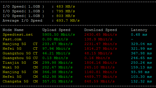
RFCHOST - 洛杉矶CN2 GIA VPS季付23.9美元起 100Mbps带宽
RFCHOST,这个服务商我们可能有一些朋友知道的。不要看官网是英文就以为是老外服务商,实际上这个服务商公司在上海。我们实际上看到的很多商家,有的是繁体,有的是英文,实际上很多都是我们国人朋友做的,有的甚至还做好几个品牌域名,实际上都是一个公司。对于RFCHOST商家还是第一次分享他们家的信息,公司成立大约2015年左右。目前RFCHOST洛杉矶机房VPS正进行优惠促销,采用CN2优化线路,电信双...

fastreport2.5为你推荐
-
巴尔扎克搜狗拼音输入法4徐州微信5参考手册NDXS和ND5XS网络音频播放器中文目录namesgraph设备ipad支持ipad支持ipad支持ipad重庆网通重庆联通宽带win7telnetwindows7的TELNET服务在哪里开启啊