电流四川宜宾山体塌方砸中3车
四川宜宾山体塌方砸中3车 时间:2021-04-25 阅读:()
AnIMPORTANTNOTICEattheendofthisdatasheetaddressesavailability,warranty,changes,useinsafety-criticalapplications,intellectualpropertymattersandotherimportantdisclaimers.
PRODUCTIONDATA.
EnglishDataSheet:SLOS846DRV8303ZHCSBP4C–SEPTEMBER2013–REVISEDDECEMBER2016具具有有两两个个电电流流分分流流放放大大器器的的DRV8303三三相相栅栅极极驱驱动动器器11特特性性16V至60V工作电源电压范围1.
7A拉电流和2.
3A灌电流栅极驱动电流能力具有用于降低EMI的转换率控制支持100%占空比的自举栅极驱动器6种或3种脉宽调制(PWM)输入模式具有可调节增益和偏移的双集成电流分流放大器支持3.
3V和5V接口串行外设接口(SPI)DRV8303中的特性:–可编程死区控制(DTC)–可编程过流保护(OCP)–PVDD和GVDD欠压锁定(UVLO)–GVDD过压锁定(OVLO)–过热警告/关断(OTW/OTS)–通过nFAULT、nOCTW和SPI寄存器进行报告2应应用用三相无刷直流(BLDC)电机和永磁同步电机(PMSM)CPAP和泵电动自行车电动工具机器人和遥控(RC)玩具工业自动化3说说明明DRV8303是一款适用于三相电机驱动应用的栅极驱动器IC.
该器件提供三个半桥驱动器,每个驱动器能够驱动两个N通道MOSFET.
该器件最高支持1.
7A拉电流和2.
3A峰值电流.
DRV8303可在6V至60V的宽电源范围内,在单一电源供电下运行.
它采用自举栅极驱动器架构和涓流充电电路来支持100%占空比.
DRV8303在切换高侧或低侧MOSFET时使用自动握手机制,以防止发生电流击穿.
高侧和低侧MOSFET的集成VDS感测用于防止外部功率级出现过流现象.
DRV8303具有两个针对电流进行精确测量的分流放大器.
这两个放大器支持双向电流感测,可提供高达3V的可调节输出失调电压.
串行外设接口(SPI)提供详细的故障报告和灵活的参数设置,例如电流分流放大器的增益选项和栅极驱动器的转换率控制.
器器件件信信息息(1)器器件件型型号号封封装装封封装装尺尺寸寸((标标称称值值))DRV8303TSSOP(48)12.
50mmx6.
10mm(1)要了解所有可用封装,请参见数据表末尾的可订购产品附录.
简简化化电电路路原原理理图图2DRV8303ZHCSBP4C–SEPTEMBER2013–REVISEDDECEMBER2016www.
ti.
com.
cnCopyright2013–2016,TexasInstrumentsIncorporated目目录录1特特性性.
12应应用用.
13说说明明.
14修修订订历历史史记记录录25PinConfigurationandFunctions.
36Specifications.
56.
1AbsoluteMaximumRatings56.
2ESDRatings.
56.
3RecommendedOperatingConditions.
66.
4ThermalInformation.
66.
5ElectricalCharacteristics.
66.
6CurrentShuntAmplifierCharacteristics.
86.
7SPICharacteristics(SlaveModeOnly)86.
8GateTimingandProtectionSwitchingCharacteristics96.
9TypicalCharacteristics.
107DetailedDescription117.
1Overview117.
2FunctionalBlockDiagram127.
3FeatureDescription.
137.
4DeviceFunctionalModes.
177.
5Programming.
197.
6RegisterMaps.
208ApplicationandImplementation228.
1ApplicationInformation.
228.
2TypicalApplication239PowerSupplyRecommendations.
269.
1BulkCapacitance2610Layout.
2710.
1LayoutGuidelines2710.
2LayoutExample2811器器件件和和文文档档支支持持2911.
1文档支持.
2911.
2接收文档更新通知2911.
3社区资源.
2911.
4商标.
2911.
5静电放电警告.
2911.
6Glossary.
2912机机械械、、封封装装和和可可订订购购信信息息.
294修修订订历历史史记记录录注:之前版本的页码可能与当前版本有所不同.
ChangesfromRevisionB(November2015)toRevisionCPageAddedthemaximumvoltagedifferenceandmaximumvoltageparametersfortheBST_X,GH_X,SL_X,andSH_XpinsintheAbsoluteMaximumRatingstable5已添加文档支持和接收文档更新通知部分.
29ChangesfromRevisionA(October2013)toRevisionBPage已添加ESD额定值表、特性说明部分、器件功能模式、应用和实施部分、电源相关建议部分、布局部分、器件和文档支持部分以及机械、封装和可订购信息部分1更新了标题.
1VPVDDabsolutemaxvoltageratingreducedfrom70Vto65V5ClarificationmadeonhowtheOCPstatusbitsreportinOvercurrentProtection(OCP)andReporting15UpdatetoPVDDundervoltageprotectioninUndervoltageProtection(UVLO)describingspecifictransientbrownoutissue.
16UpdatetoEN_GATEpinfunctionaldescriptioninEN_GATEclarifyingproperEN_GATEresetpulselengths.
17Addedgatedriverpower-upsequencingerrata223DRV8303www.
ti.
com.
cnZHCSBP4C–SEPTEMBER2013–REVISEDDECEMBER2016Copyright2013–2016,TexasInstrumentsIncorporated5PinConfigurationandFunctionsDCAPackage48-PinTSSOPPadDownTopViewPinFunctionsPINI/ODESCRIPTIONNO.
NAME1nOCTWOOvercurrentandovertemperaturewarningindicator.
Thisoutputisopendrainwithexternalpullupresistorrequired.
ProgrammableoutputmodethroughSPIregisters.
2nFAULTOFaultreportindicator.
Thisoutputisopendrainwithexternalpullupresistorrequired.
3DTCIDead-timeadjustmentwithexternalresistortoGND4nSCSISPIchipselect5SDIISPIinput6SDOOSPIoutput7SCLKISPIclocksignal8DC_CALIWhenDC_CALishigh,deviceshortsinputsofshuntamplifiersanddisconnectsloads.
DCoffsetcalibrationcanbedonethroughexternalmicrocontroller.
9GVDDPInternalgatedrivervoltageregulator.
GVDDcapshouldconnecttoGND10CP1PChargepumppin1,ceramiccapshouldbeusedbetweenCP1andCP211CP2PChargepumppin2,ceramiccapshouldbeusedbetweenCP1andCP212EN_GATEIEnablegatedriverandcurrentshuntamplifiers.
13INH_AIPWMInputsignal(highside),half-bridgeA14INL_AIPWMInputsignal(lowside),half-bridgeA15INH_BIPWMInputsignal(highside),half-bridgeB16INL_BIPWMInputsignal(lowside),half-bridgeB17INH_CIPWMInputsignal(highside),half-bridgeC18INL_CIPWMInputsignal(lowside),half-bridgeC4DRV8303ZHCSBP4C–SEPTEMBER2013–REVISEDDECEMBER2016www.
ti.
com.
cnCopyright2013–2016,TexasInstrumentsIncorporatedPinFunctions(continued)PINI/ODESCRIPTIONNO.
NAME19DVDDPInternal3.
3-Vsupplyvoltage.
DVDDcapshouldconnecttoAGND.
Thisisanoutput,butnotspecifiedtodriveexternalcircuitry.
20REFIReferencevoltagetosetoutputofshuntamplifierswithabiasvoltagewhichequalstohalfofthevoltagesetonthispin.
ConnecttoADCreferenceinmicrocontroller.
21SO1OOutputofcurrentamplifier122SO2OOutputofcurrentamplifier223AVDDPInternal6-Vsupplyvoltage,AVDDcapacitorshouldalwaysbeinstalledandconnectedtoAGND.
Thisisanoutput,butnotspecifiedtodriveexternalcircuitry.
24AGNDPAnaloggroundpin25PVDDPPowersupplypinforgatedriver,currentshuntamplifier,andSPIcommunication.
PVDDcapshouldconnecttoGND26SP2IInputofcurrentamplifier2(connectingtopositiveinputofamplifier).
Recommendtoconnecttogroundsideofthesenseresistorforthebestcommonmoderejection.
27SN2IInputofcurrentamplifier2(connectingtonegativeinputofamplifier).
28SP1IInputofcurrentamplifier1(connectingtopositiveinputofamplifier).
Recommendtoconnecttogroundsideofthesenseresistorforthebestcommonmoderejection.
29SN1IInputofcurrentamplifier1(connectingtonegativeinputofamplifier).
30SL_CILow-SideMOSFETsourceconnection,half-bridgeC.
Low-sideVDSmeasuredbetweenthispinandSH_C.
31GL_COGatedriveoutputforLow-SideMOSFET,half-bridgeC32SH_CIHigh-SideMOSFETsourceconnection,half-bridgeC.
High-sideVDSmeasuredbetweenthispinandPVDD.
33GH_COGatedriveoutputforHigh-SideMOSFET,half-bridgeC34BST_CPBootstrapcapacitorpinforhalf-bridgeC35SL_BILow-SideMOSFETsourceconnection,half-bridgeB.
Low-sideVDSmeasuredbetweenthispinandSH_B.
36GL_BOGatedriveoutputforLow-SideMOSFET,half-bridgeB37SH_BIHigh-SideMOSFETsourceconnection,half-bridgeB.
High-sideVDSmeasuredbetweenthispinandPVDD.
38GH_BOGatedriveoutputforHigh-SideMOSFET,half-bridgeB39BST_BPBootstrapcappinforhalf-bridgeB40SL_AILow-SideMOSFETsourceconnection,half-bridgeA.
Low-sideVDSmeasuredbetweenthispinandSH_A.
41GL_AOGatedriveoutputforLow-SideMOSFET,half-bridgeA42SH_AIHigh-SideMOSFETsourceconnection,half-bridgeA.
High-sideVDSmeasuredbetweenthispinandPVDD.
43GH_AOGatedriveoutputforHigh-SideMOSFET,half-bridgeA44BST_APBootstrapcapacitorpinforhalf-bridgeA45VDD_SPIISPIsupplypintosupport3.
3Vor5Vlogic.
Connecttoeither3.
3Vor5V.
469GNDOGNDpin.
TheexposedpowerpadmustbeelectricallyconnectedtogroundplanethroughsolderingtoPCBforproperoperationandconnectedtobottomsideofPCBthroughviasforbetterthermalspreading.
474849GND(PWR_PAD)5DRV8303www.
ti.
com.
cnZHCSBP4C–SEPTEMBER2013–REVISEDDECEMBER2016Copyright2013–2016,TexasInstrumentsIncorporated(1)StressesbeyondthoselistedunderAbsoluteMaximumRatingsmaycausepermanentdamagetothedevice.
Thesearestressratingsonly,whichdonotimplyfunctionaloperationofthedeviceattheseoranyotherconditionsbeyondthoseindicatedunderRecommendedOperatingConditions.
Exposuretoabsolute-maximum-ratedconditionsforextendedperiodsmayaffectdevicereliability.
6Specifications6.
1AbsoluteMaximumRatingsoveroperatingfree-airtemperaturerange(unlessotherwisenoted)(1)MINMAXUNITVPVDDSupplyvoltageRelativetoPGND–0.
365VMaximumsupply-voltageramprateVoltagerisinguptoPVDDMAX1V/sVPGNDMaximumvoltagebetweenPGNDandGND–0.
30.
3VVOPA_INVoltageforSPxandSNxpins–0.
60.
6VVLOGICInputvoltageforlogicanddigitalpins(INH_A,INL_A,INH_B,INL_B,INH_C,INL_C,EN_GATE,SCLK,SDI,SCS,DC_CAL)–0.
37VVGVDDMaximumvoltageforGVDDpin13.
2VVAVDDMaximumvoltageforAVDDpin8VVDVDDMaximumvoltageforDVDDpin3.
6VVVDD_SPIMaximumvoltageforVDD_SPIpin7VVSDOMaximumvoltageforSDOpinVDD_SPI+0.
3VVREFMaximumreferencevoltageforcurrentamplifier7VVBST_MAXMaximumvoltageforBST_XPin–0.
380VVBST_DIFFMaximumvoltagedifferencefor(BST_X-SH_X)and(BST_X-GH_X)–0.
314.
5VVGH_MAXMaximumvoltageforGH_Xpin–0.
380VVGH_DIFMaximumvoltagedifferencefor(GH_X-SH_X)–0.
314.
5VVGL_MAXMaximumvoltageforGL_Xpin–0.
313.
2VVGL_DIFMaximumvoltagedifferencefor(GL_X-SL_X)–0.
313.
2VVSH_MAXMaximumvoltageforSH_Xpin–2PVDD+2VVSL_MAXMaximumvoltageforSL_Xpin–0.
60.
6VIIN_MAXMaximumcurrentforalldigitalandanaloginputs(INH_A,INL_A,INH_B,INL_B,INH_C,INL_C,SCLK,SCS,SDI,EN_GATE,DC_CAL,DTC)–11mAISINK_MAXMaximumsinkingcurrentforopen-drainpins(nFAULTandnOCTWpins)7mAIREFMaximumcurrentforREFpin100ATstgStoragetemperature–55150°C(1)JEDECdocumentJEP155statesthat500-VHBMallowssafemanufacturingwithastandardESDcontrolprocess.
(2)JEDECdocumentJEP157statesthat250-VCDMallowssafemanufacturingwithastandardESDcontrolprocess.
6.
2ESDRatingsVALUEUNITV(ESD)ElectrostaticdischargeHumanbodymodel(HBM),perANSI/ESDA/JEDECJS-001(1)±2000VChargeddevicemodel(CDM),perJEDECspecificationJESD22-C101(2)±5006DRV8303ZHCSBP4C–SEPTEMBER2013–REVISEDDECEMBER2016www.
ti.
com.
cnCopyright2013–2016,TexasInstrumentsIncorporated6.
3RecommendedOperatingConditionsOveroperatingfree-airtemperaturerange(unlessotherwisenoted).
MINNOMMAXUNITVPVDDDCsupplyvoltagePVDDfornormaloperationRelativetoPGND660VIDIN_ENInputcurrentofdigitalpinswhenEN_GATEishigh100AIDIN_DISInputcurrentofdigitalpinswhenEN_GATEislow1ACO_OPAMaximumoutputcapacitanceonoutputsofshuntamplifier20pFRDTCDeadtimecontrolresistor.
Timerangeis50ns(–GND)to500ns(150kΩ)withalinearapproximation.
0150kIFAULTnFAULTpinsinkcurrent.
OpendrainV=0.
4V2mAIOCTWnOCTWpinsinkcurrent.
OpendrainV=0.
4V2mAVREFExternalvoltagereferencevoltageforcurrentshuntamplifiers26VfgateOperatingswitchingfrequencyofgatedriverQg(TOT)=25nCortotal30-mAgatedriveaveragecurrent200kHzIgateTotalaveragegatedrivecurrent30mATAAmbienttemperature–40125°C(1)Formoreinformationabouttraditionalandnewthermalmetrics,seetheSemiconductorandICPackageThermalMetricsapplicationreport.
6.
4ThermalInformationTHERMALMETRIC(1)DRV8303UNITDCA(TSSOP)48PINSRθJAJunction-to-ambientthermalresistance30.
3°C/WRθJC(top)Junction-to-case(top)thermalresistance33.
5°C/WRθJBJunction-to-boardthermalresistance17.
5°C/WψJTJunction-to-topcharacterizationparameter0.
9°C/WψJBJunction-to-boardcharacterizationparameter7.
2°C/WRθJC(bot)Junction-to-case(bottom)thermalresistance0.
9°C/W6.
5ElectricalCharacteristicsPVDD=6Vto60V,TC=25°C,unlessspecifiedundertestconditionPARAMETERTESTCONDITIONSMINTYPMAXUNITINPUTPINS:INH_X,INL_X,SCS,SDI,SCLK,EN_GATE,DC_CALVIHHighinputthreshold2VVILLowinputthreshold0.
8VRPULL_DOWN–INTERNALPULLDOWNRESISTORFORGATEDRIVERINPUTSREN_GATEInternalpulldownresistorforEN_GATE100kΩRINH_XInternalpulldownresistorforhighsidePWMs(INH_A,INH_B,andINH_C)EN_GATEhigh100kΩRINH_XInternalpulldownresistorforlowsidePWMs(INL_A,INL_B,andINL_C)EN_GATEhigh100kΩRSCSInternalpulldownresistorfornSCSEN_GATEhigh100kΩRSDIInternalpulldownresistorforSDIEN_GATEhigh100kΩRDC_CALInternalpulldownresistorforDC_CALEN_GATEhigh100kΩRSCLKInternalpulldownresistorforSCLKEN_GATEhigh100kΩOUTPUTPINS:nFAULTANDnOCTWVOLLow-outputthresholdIO=2mA0.
4VVOHHigh-outputthresholdExternal47-kΩpullupresistorconnectedto3-5.
5V2.
4V7DRV8303www.
ti.
com.
cnZHCSBP4C–SEPTEMBER2013–REVISEDDECEMBER2016Copyright2013–2016,TexasInstrumentsIncorporatedElectricalCharacteristics(continued)PVDD=6Vto60V,TC=25°C,unlessspecifiedundertestconditionPARAMETERTESTCONDITIONSMINTYPMAXUNIT(1)ReducedAVDDvoltagerangeresultsinlimitationsonsettingsforovercurrentprotection.
SeeTable12.
IOHLeakagecurrentonopendrainpinswhenlogichigh(nFAULTandnOCTW)1AGATEDRIVEOUTPUT:GH_A,GH_B,GH_C,GL_A,GL_B,GL_CVGX_NORMGatedriverVgsvoltagePVDD=8Vto60V,Igate=30mA,CCP=22nF9.
511.
5VPVDD=8Vto60V,Igate=30mA,CCP=220nF9.
511.
5VGX_MINGatedriverVgsvoltagePVDD=6Vto8V,Igate=15mA,CCP=22nF8.
8VPVDD=6Vto8V,Igate=30mA,CCP=220nF8.
3Ioso1Maximumsourcecurrentsetting1,peakVgsofFETequalsto2V.
REG0x021.
7AIosi1Maximumsinkcurrentsetting1,peakVgsofFETequalsto8V.
REG0x022.
3AIoso2Sourcecurrentsetting2,peakVgsofFETequalsto2V.
REG0x020.
7AIosi2Sinkcurrentsetting2,peakVgsofFETequalsto8V.
REG0x021AIoso3Sourcecurrentsetting3,peakVgsofFETequalsto2V.
REG0x020.
25AIosi3Sinkcurrentsetting3,peakVgsofFETequalsto8V.
REG0x020.
5ARgate_offGateoutputimpedanceduringstandbymodewhenEN_GATElow(pinsGH_x,GL_x)1.
62.
4kΩSUPPLYCURRENTSIPVDD_STBPVDDsupplycurrent,standbyEN_GATEislow.
PVDD=8V2050AIPVDD_OPPVDDsupplycurrent,operatingEN_GATEishigh,noloadongatedriveoutput,switchingat10kHz,100-nCgatecharge15mAIPVDD_HIZPVDDsupplycurrent,Hi-ZEN_GATEishigh,gatenotswitching2510mAINTERNALREGULATORVOLTAGEAVDDAVDDvoltagePVDD=8Vto60V66.
57VPVDD=6Vto8V5.
56DVDDDVDDvoltage33.
33.
6VVOLTAGEPROTECTIONVPVDD_UVUndervoltageprotectionlimit,PVDD6VVGVDD_UVUndervoltageprotectionlimit,GVDD7.
5VVGVDD_OVOvervoltageprotectionlimit,GVDD16VCURRENTPROTECTION,(VDSSENSING)VDS_OCDrain-sourcevoltageprotectionlimitPVDD=8Vto60V0.
1252.
4VPVDD=6Vto8V(1)0.
1251.
491TOCOCsensingresponsetime1.
5sTOC_PULSEnOCTWpinreportingpulsestretchlengthforOCevent64sTEMPERATUREPROTECTIONOTW_CLRJunctiontemperatureforresettingovertemperaturewarning115°COTW_SET/OTSD_CLRJunctiontemperatureforovertemperaturewarningandresettingovertemperatureshutdown130°COTSD_SETJunctiontemperatureforovertemperatureshutdown150°C8DRV8303ZHCSBP4C–SEPTEMBER2013–REVISEDDECEMBER2016www.
ti.
com.
cnCopyright2013–2016,TexasInstrumentsIncorporated6.
6CurrentShuntAmplifierCharacteristicsOveroperatingfree-airtemperaturerange.
PARAMETERTESTCONDITIONSMINTYPMAXUNITG1Gainoption1Tc=–40°Cto125°C9.
51010.
5V/VG2Gainoption2Tc=–40°Cto125°C182021V/VG3GainOption3Tc=–40°Cto125°C384042V/VG4GainOption4Tc=–40°Cto125°C758085V/VTsettlingSettlingtimeto1%Tc=0to60°C,G=10,Vstep=2V300nsTsettlingSettlingtimeto1%Tc=0to60°C,G=20,Vstep=2V600nsTsettlingSettlingtimeto1%Tc=0to60°C,G=40,Vstep=2V1.
2sTsettlingSettlingtimeto1%Tc=0to60°C,G=80,Vstep=2V2.
4sVswingOutputswinglinearrange0.
35.
7VSlewRateG=1010V/sDC_offsetOffseterrorRTIG=10withinputshorted4mVDrift_offsetOffsetdriftRTI10V/CIbiasInputbiascurrent100AVin_comCommoninputmoderange–0.
150.
15VVin_difDifferentialinputrange–0.
30.
3VVo_biasOutputbiasWithzeroinputcurrent,VREFupto6V–0.
5%0.
5*Vref0.
5%VCMRR_OVOverallCMRRwithgainresistormismatchCMRRatDC,gain=107085dB6.
7SPICharacteristics(SlaveModeOnly)MINNOMMAXUNITtSPI_READYSPIreadyafterEN_GATEtransitionstoHIGHPVDD>6V510mstCLKMinimumSPIclockperiod100nstCLKHClockhightimeSeeFigure140nstCLKLClocklowtimeSeeFigure140nstSU_SDISDIinputdatasetuptime20nstHD_SDISDIinputdataholdtime30nstD_SDOSDOoutputdatadelaytime,CLKhightoSDOvalidCL=20pF20nstHD_SDOSDOoutputdataholdtimeSeeFigure140nstSU_SCSSCSsetuptimeSeeFigure150nstHD_SCSSCSholdtime50nstHI_SCSSCSminimumhightimebeforeSCSactivelow40nstACCSCSaccesstime,SCSlowtoSDOoutofhighimpedance10nstDISSCSdisabletime,SCShightoSDOhighimpedance10ns9DRV8303www.
ti.
com.
cnZHCSBP4C–SEPTEMBER2013–REVISEDDECEMBER2016Copyright2013–2016,TexasInstrumentsIncorporated(1)Deadtimeprogrammingdefinition:AdjustabledelayfromGH_xfallingedgetoGL_Xrisingedge,andGL_XfallingedgetoGH_Xrisingedge.
Thisisaminimumdead-timeinsertion.
Itisnotaddedtothevaluesetbythemicrocontrollerexternally.
6.
8GateTimingandProtectionSwitchingCharacteristicsPARAMETERTESTCONDITIONSMINTYPMAXUNITTIMING,OUTPUTPINStpd,If-OPositiveinputfallingtoGH_xfallingCL=1nF,50%to50%45nstpd,Ir-OPositiveinputrisingtoGL_xfallingCL=1nF,50%to50%45nstd_minMinimumdeadtimeafterhandshaking(1)50nstdtpDeadtimeWithRDTCsettodifferentvalues50500nstGDrRisetime,gatedriveoutputCL=1nF,10%to90%25nstGDFFalltime,gatedriveoutputCL=1nF,90%to10%25nstON_MINMinimumonpulseNotincludinghandshakecommunication.
Hi-Ztoonstate,outputofgatedriver50nstpd_matchPropagationdelaymatchingbetweenhighsideandlowside5nstdt_matchDeadtimematching5nsTIMING,PROTECTIONANDCONTROLtpd,R_GATE-OPStart-uptime,fromEN_GATEactivehightodevicereadyfornormaloperationPVDDisupbeforestartup,allchargepumpcapsandregulatorcapacitorsasintheRecommendedOperatingConditions510mstpd,R_GATE-QuickIfEN_GATEgoesfromhightolowandbacktohighstatewithinquickresettime,itwillonlyresetallfaultsandgatedriverwithoutpoweringdownchargepump,currentamp,andrelatedinternalvoltageregulators.
Maximumlowpulsetime10stpd,E-LDelay,erroreventtoallgateslow200nstpd,E-FAULTDelay,erroreventtoFAULTlow200nsFigure1.
SPISlaveModeTimingDefinition10DRV8303ZHCSBP4C–SEPTEMBER2013–REVISEDDECEMBER2016www.
ti.
com.
cnCopyright2013–2016,TexasInstrumentsIncorporatedFigure2.
SPISlaveModeTimingDiagram6.
9TypicalCharacteristicsPVDD=8VEN_GATE=LOWFigure3.
IPVDD1vsTemperaturePVDD=8VEN_GATE=HIGHFigure4.
GVDDvsTemperaturePVDD=60VEN_GATE=HIGHFigure5.
GVDDvsTemperature11DRV8303www.
ti.
com.
cnZHCSBP4C–SEPTEMBER2013–REVISEDDECEMBER2016Copyright2013–2016,TexasInstrumentsIncorporated7DetailedDescription7.
1OverviewTheDRV8303isa6-Vto60-V,gatedriverICforthree-phasemotordriveapplications.
Thisdevicereducesexternalcomponentcountbyintegratingthreehalf-bridgedriversandtwocurrentshuntamplifiers.
TheDRV8303providesovercurrent,over-temperature,andundervoltageprotection.
FaultconditionsareindicatedthroughthenFAULTandnOCTWpinsinadditiontotheSPIregisters.
AdjustabledeadtimecontrolandpeakgatedrivecurrentallowsforfinelytuningtheswitchingoftheexternalMOSFETs.
Internalhandshakingisusedtopreventthroughcurrent.
VDSsensingoftheexternalMOSFETsallowsfortheDRV8303todetectovercurrentconditionsandrespondappropriately.
IndividualMOSFETovercurrentconditionsarereportedthroughtheSPIstatusregisters.
12DRV8303ZHCSBP4C–SEPTEMBER2013–REVISEDDECEMBER2016www.
ti.
com.
cnCopyright2013–2016,TexasInstrumentsIncorporated7.
2FunctionalBlockDiagram13DRV8303www.
ti.
com.
cnZHCSBP4C–SEPTEMBER2013–REVISEDDECEMBER2016Copyright2013–2016,TexasInstrumentsIncorporated7.
3FeatureDescriptionThefollowingsectionsdescribetheDRV8303features.
7.
3.
1Three-PhaseGateDriverThehalf-bridgedriversuseabootstrapconfigurationwithatricklechargepumptosupport100%dutycycleoperation.
Eachhalf-bridgeisconfiguredtodrivetwoN-channelMOSFETs,oneforthehigh-sideandoneforthelow-side.
Thehalf-bridgedriverscanbeusedincombinationtodrivea3-phasemotororseparatelytodrivevariousotherloads.
ThepeakgatedrivecurrentandinternaldeadtimesareadjustabletoaccommodateavarietyofexternalMOSFETsandapplications.
ThepeakgatedrivecurrentissetthrougharegistersettingandthedeadtimeisadjustedwithanexternalresistorontheDTCpin.
ShortingtheDTCpintogroundwillprovidetheminimumdeadtime(50ns).
ThereisaninternalhandshakebetweenthehighsideandlowsideMOSFETsduringswitchingtransitionstopreventcurrentshootthrough.
Thethree-phasegatedrivercanprovideupto30mAofaveragegatedrivecurrent.
Thiswillsupportswitchingfrequenciesupto200kHzwhentheMOSFETQg=25nC.
EachMOSFETgatedriverhasaVDSsensingcircuitforovercurrentprotection.
ThesensecircuitmeasuresthevoltagefromthedraintothesourceoftheexternalMOSFETswhiletheMOSFETisenabled.
Thisvoltageiscomparedagainsttheprogrammedtrippointtodetermineifanovercurrenteventhasoccurred.
Thehigh-sidesenseisbetweenthePVDD1andSH_Xpins.
Thelow-sidesenseisbetweentheSH_XandSL_Xpins.
Ensuringadifferential,lowimpedanceconnectiontotheexternalMOSFETsfortheselineswillhelpprovideaccurateVDSsensing.
TheDRV8303allowsforboth6-PWMand3-PWMcontrolthrougharegistersetting.
Table1.
6-PWMModeINL_XINH_XGL_XGH_X00LL01LH10HL11LLTable2.
3-PWMModeINL_XINH_XGL_XGH_XX0HLX1LH(1)VCCisthelogicsupplytotheMCUTable3.
GateDriverExternalComponentsNAMEPIN1PIN2RECOMMENDEDRnOCTWnOCTWVCC(1)≥10kRnFAULTnFAULTVCC(1)≥10kRDTCDTCGND(PowerPAD)0to150k(50nsto500ns)CGVDDGVDDGND(PowerPAD)2.
2-F(20%)ceramic,≥16VCCPCP1CP20.
022-F(20%)ceramic,ratedforPVDDCDVDDDVDDAGND1-F(20%)ceramic,≥6.
3VCAVDDAVDDAGND1-F(20%)ceramic,≥10VCPVDDPVDDGND(PowerPAD)≥4.
7-F(20%)ceramic,ratedforPVDDCBST_XBST_XSH_X0.
1-F(20%)ceramic,≥16V14DRV8303ZHCSBP4C–SEPTEMBER2013–REVISEDDECEMBER2016www.
ti.
com.
cnCopyright2013–2016,TexasInstrumentsIncorporated7.
3.
2CurrentShuntAmplifiersTheDRV8303includestwohighperformancecurrentshuntamplifierstoaccuratelow-side,inlinecurrentmeasurement.
Thecurrentshuntamplifiershave4programmableGAINsettingsthroughtheSPIregisters.
Theseare10,20,40,and80V/V.
Theyprovideoutputoffsetupto3Vtosupportbidirectionalcurrentsensing.
Theoffsetissettohalfthevoltageonthereferencepin(REF).
TominimizeDCoffsetanddriftovertemperatureacalibrationmethodisprovidedthrougheithertheDC_CALpinorSPIregister.
WhenDCcalibrationisenabled,thedevicewillshorttheinputofthecurrentshuntamplifieranddisconnecttheload.
DCcalibrationcanbedoneatanytime,evenduringMOSFETswitching,becausetheloadisdisconnected.
Forthebestresults,performtheDCcalibrationduringtheswitchingOFFperiod,whennoloadispresent,toreducethepotentialnoiseimpacttotheamplifier.
UseEquation1tocalculatetheoutputofthecurrentshuntamplifier.
whereVREFisthereferencevoltage(REFpin)Gisthegainoftheamplifier(10,20,40,or80V/V)SNXandSPxaretheinputsofchannelx.
SPxshouldconnecttothegroundsideofthesenseresistorforthenestcommonmoderejection.
(1)Figure6showsthesimplifiedblockdiagramforthecurrentshuntamplifier.
Figure6.
CurrentShuntAmplifierSimplifiedBlockDiagram15DRV8303www.
ti.
com.
cnZHCSBP4C–SEPTEMBER2013–REVISEDDECEMBER2016Copyright2013–2016,TexasInstrumentsIncorporated7.
3.
3ProtectionFeaturesTheDRV8303providesabroadrangeofprotectionfeaturesandfaultconditionreporting.
TheDRV8303hasundervoltageandover-temperatureprotectionfortheIC.
ItalsohasovercurrentandundervoltageprotectionfortheMOSFETpowerstage.
InfaultshutdownconditionsallgatedriveroutputswillbeheldlowtoensuretheexternalMOSFETsareinahighimpedancestate.
7.
3.
3.
1PowerStageProtectionTheDRV8303providesover-currentandundervoltageprotectionfortheMOSFETpowerstage.
Duringfaultshutdownconditions,allgatedriveroutputswillbekeptlowtoensureexternalFETsathighimpedancestate.
7.
3.
3.
2OvercurrentProtection(OCP)andReportingToprotectthepowerstagefromdamageduetoexcessivecurrents,VDSsensingcircuitryisimplementedintheDRV8303.
BasedontheRDS(on)oftheexternalMOSFETsandthemaximumallowedIDS,avoltagethresholdcanbedeterminedtotriggertheovercurrentprotectionfeatureswhenexceeded.
ThevoltagethresholdisprogrammedthroughtheSPIregisters.
Overcurrentprotectionshouldbeusedasaprotectionschemeonly;itisnotintendedasaprecisecurrentregulationscheme.
Therecanbeuptoa20%toleranceacrosschannelsfortheVDStrippoint.
VDS=IDS*RDS(ON)(2)TheVDSsensecircuitmeasuresthevoltagefromthedraintothesourceoftheexternalMOSFETwhiletheMOSFETisenabled.
Thehigh-sidesenseisbetweenthePVDDandSH_Xpins.
Thelow-sidesenseisbetweentheSH_XandSL_Xpins.
Ensuringadifferential,lowimpedanceconnectiontotheexternalMOSFETsfortheselineswillhelpprovideaccurateVDSsensing.
Therearefourdifferentovercurrentmodes(OC_MODE)thatcanbesetthroughtheSPIregisters.
TheOCstatusbitsoperateinlatchedmode.
WhenanovercurrentconditionoccursthecorrespondingOCstatusbitwilllatchintheDRV8303registersuntilthefaultisreset.
1.
CurrentLimitMode:Incurrentlimitmodethedeviceusescurrentlimitinginsteadofdeviceshutdownduringanovercurrentevent.
InthismodethedevicereportsovercurrenteventsthroughthenOCTWpin.
ThenOCTWpinwillbeheldlowforamaximum64-speriod(internaltimer)oruntilthenextPWMcycle.
IfanotherovercurrenteventistriggeredfromanotherMOSFET,duringapreviousovercurrentevent,thereportingwillcontinueforanother64-speriod(internaltimerwillrestart)oruntilbothPWMsignalscycle.
TheassociatedstatusbitwillbeassertedfortheMOSFETinwhichtheovercurrentwasdetected.
Therearetwocurrentcontrolsettingsincurrentlimitmode.
ThesearesetbyonebitintheSPIregisters.
Thedefaultmodeiscyclebycycle(CBC).
–Cycle-By-CycleMode(CBC):InCBCmode,theMOSFETonwhichovercurrenthasbeendetectedonwillshutoffuntilthenextPWMcycle.
–Off-TimeControlMode:InOff-Timemode,theMOSFETinwhichovercurrenthasbeendetectedisdisabledfora64-speriod(setbyinternaltimer).
IfovercurrentisdetectedinanotherMOSFET,thetimerwillberesetforanother64-speriodandbothMOSFETswillbedisabledfortheduration.
Duringthisperiod,normaloperationcanberestoredforaspecificMOSFETwithacorrespondingPWMcycle.
2.
OCLatchShutDownMode:Whenanovercurrenteventoccurs,boththehigh-sideandlow-sideMOSFETswillbedisabledinthecorrespondinghalf-bridge.
ThenFAULTpin,nFAULTstatusbit,andOCstatusbitfortheMOSFETinwhichtheovercurrentwasdetectedwilllatchuntilthefaultisresetthroughtheGATE_RESETbitoraquickEN_GATEresetpulse.
3.
ReportOnlyMode:Noprotectiveactionwillbetakeninthismodewhenanovercurrenteventoccurs.
TheovercurrenteventwillbereportedthroughthenOCTWpin(64-spulse)andSPIstatusregister.
TheexternalMCUshouldtakeactionbasedonitsowncontrolalgorithm.
4.
OCDisableMode:Thedevicewillignoreandnotreportallovercurrentdetections.
7.
3.
3.
3UndervoltageProtection(UVLO)Toprotectthepoweroutputstageduringstart-up,shutdown,andotherpossibleundervoltageconditions,theDRV8303providesundervoltageprotectionbydrivingthegatedriveoutputs(GH_X,GL_X)lowwheneverPVDDorGVDDarebelowtheirundervoltagethresholds(PVDD_UV/GVDD_UV).
ThiswillputtheexternalMOSFETsinahighimpedancestate.
WhenthedeviceisinPVDD_UVitwillnotrespondtoSPIcommandsandtheSPIregisterswillreverttotheirdefaultsettings.
16DRV8303ZHCSBP4C–SEPTEMBER2013–REVISEDDECEMBER2016www.
ti.
com.
cnCopyright2013–2016,TexasInstrumentsIncorporatedAspecificPVDDundervoltagetransientbrownoutfrom13to15scancausetheDRV8303tobecomeunresponsivetoexternalinputsuntilafullpowercycle.
ThetransientconditionconsistsofhavingPVDDgreaterthanthePVDD_UVlevelandthenPVDDdroppingbelowthePVDD_UVlevelforaspecificperiodof13to15s.
Transientsshorterorlongerthan13to15swillnotaffectthenormaloperationoftheundervoltageprotection.
AdditionalbulkcapacitancecanbeaddedtoPVDDtoreduceundervoltagetransients.
7.
3.
3.
4OvervoltageProtection(GVDD_OV)ThedevicewillshutdownboththegatedriverandchargepumpiftheGVDDvoltageexceedstheGVDD_OVthresholdtopreventpotentialissuesrelatedtotheGVDDpinorthechargepump(forexample,shortofexternalGVDDcaporchargepump).
ThefaultisalatchedfaultandcanonlyberesetthrougharesettransitionontheEN_GATEpin.
7.
3.
3.
5OvertemperatureProtectionAtwo-levelover-temperaturedetectioncircuitisimplemented:Level1:overtemperaturewarning(OTW)OTWisreportedthroughnOCTWpin(over-current-temperaturewarning)fordefaultsetting.
OCTWpincanbesettoreportOTWorOCWonlythroughSPIcommand.
SeeSPIRegistersection.
Level2:overtemperature(OT)latchedshutdownofgatedriverandchargepump(OTSD_GATE)FaultwillbereportedtonFAULTpin.
Thisisalatchedshutdown,sogatedriverwillnotberecoveredautomaticallyevenOTconditionisnotpresentanymore.
AnEN_GATEresetthroughpinorSPI(RESET_GATE)isrequiredtorecovergatedrivertonormaloperationaftertemperaturegoesbelowapresetvalue,tOTSD_CLR.
SPIoperationisstillavailableandregistersettingswillberemaininginthedeviceduringOTSDoperationaslongasPVDDisstillwithindefinedoperationrange.
7.
3.
3.
6FaultandProtectionHandlingThenFAULTpinindicatesanerroreventwithshutdownhasoccurredsuchasover-current,over-temperature,overvoltage,orundervoltage.
NotethatnFAULTisanopen-drainsignal.
nFAULTwillgohighwhengatedriverisreadyforPWMsignal(internalEN_GATEgoeshigh)duringstartup.
ThenOCTWpinindicatesovercurrenteventandovertemperatureeventthatnotnecessaryrelatedtoshutdown.
Table4summarizesallprotectionfeaturesandtheirreportingstructure:Table4.
FaultandWarningReportingandHandlingEVENTACTIONLATCHREPORTINGONnFAULTPINREPORTINGONnOCTWPINREPORTINGINSPISTATUSREGISTERPVDDundervoltageExternalFETsHiZ;WeakpulldownofallgatedriveroutputNYNYDVDDundervoltageExternalFETsHiZ;Weakpulldownofallgatedriveroutput;Whenrecovering,resetallstatusregistersNYNNGVDDundervoltageExternalFETsHiZ;WeakpulldownofallgatedriveroutputNYNYGVDDovervoltageExternalFETsHiZ;WeakpulldownofallgatedriveroutputShutdownthechargepumpWon'trecoverandresetthroughSPIresetcommandorquickEN_GATEtogglingYYNYOTWNoneNNY(indefaultsetting)Y17DRV8303www.
ti.
com.
cnZHCSBP4C–SEPTEMBER2013–REVISEDDECEMBER2016Copyright2013–2016,TexasInstrumentsIncorporatedTable4.
FaultandWarningReportingandHandling(continued)EVENTACTIONLATCHREPORTINGONnFAULTPINREPORTINGONnOCTWPINREPORTINGINSPISTATUSREGISTEROTSD_GATEGatedriverlatchedshutdown.
WeakpulldownofallgatedriveroutputtoforceexternalFETsHiZShutdownthechargepumpYYYYExternalFEToverload–currentlimitmodeExternalFETscurrentLimiting(onlyOCdetectedFET)NNYY,indicateswhichphasehasOCExternalFEToverload–LatchmodeWeakpulldownofgatedriveroutputandPWMlogic"0"ofLSandHSinthesamephase.
ExternalFETsHiZYYYYExternalFEToverload–reportingonlymodeReportingonlyNNYY,indicateswhichphasehasOC7.
3.
4Start-UpandShutdownSequenceControlDuringpowerup,allgatedriveoutputsareheldlow.
NormaloperationofgatedriverandcurrentshuntamplifierscanbeinitiatedbytogglingEN_GATEfromalowstatetoahighstate.
Ifnoerrorsarepresent,theDRV8303isreadytoacceptPWMinputs.
GatedriveralwayshascontrolofthepowerFETseveningatedisablemodeaslongasPVDDiswithinfunctionalregion.
ThereisaninternaldiodefromSDOtoVDD_SPI,soVDD_SPIisrequiredtobepoweredtothesamepowerlevelasotherSPIdevices(ifthereisanySDOsignalfromotherdevices)allthetime.
VDD_SPIsupplyshouldbepoweredupfirstbeforeanysignalappearsatSDOpinandpowereddownaftercompletingallcommunicationsatSDOpin.
7.
4DeviceFunctionalModes7.
4.
1EN_GATEEN_GATElowisusedtoputgatedriver,chargepump,currentshuntamplifier,andinternalregulatorblocksintoalowpowerconsumptionmodetosaveenergy.
SPIcommunicationisnotsupportedduringthisstate.
DevicewillputtheMOSFEToutputstagetohighimpedancemodeaslongasPVDDisstillpresent.
WhenEN_GATEpingoestohigh,itwillgothroughapower-upsequence,andenablegatedriver,currentamplifiers,chargepump,internalregulator,andsoforth,andresetalllatchedfaultsrelatedtogatedriverblock.
ItwillalsoresetstatusregistersinSPItable.
AlllatchedfaultscanberesetwhenEN_GATEistoggledafteranerroreventunlessthefaultisstillpresent.
WhenEN_GATEgoesfromhightolow,itwillshutdowngatedriverblockimmediately,sogateoutputcanputexternalFETsinhighimpedancemode.
Itwillthenwaitfor10usbeforecompletelyshuttingdowntherestoftheblocks.
AquickfaultresetmodecanbedonebytogglingEN_GATEpinforaveryshortperiod(lessthan10s).
Thiswillpreventdevicetoshutdownotherfunctionblockssuchaschargepumpandinternalregulatorsandbringaquickerandsimplefaultrecovery.
SPIwillstillfunctionwithsuchaquickEN_GATEresetmode.
TheotherwaytoresetallthefaultsistouseSPIcommand(RESET_GATE),whichwillonlyresetgatedriverblockandalltheSPIstatusregisterswithoutshuttingdownotherfunctionblocks.
OneexceptionistoresetaGVDD_OVfault.
AquickEN_GATEquickfaultresetorSPIcommandresetdoesnotworkwithGVDD_OVfault.
AcompleteEN_GATEwithlowlevelholdinglongerthan10SisrequiredtoresetGVDD_OVfault.
TIhighlyrecommendsinspectingthesystemandboardwhenGVDD_OVoccurs.
7.
4.
2DTCDeadtimecanbeprogrammedthroughDTCpin.
AresistorshouldbeconnectedfromDTCtogroundtocontrolthedeadtime.
Deadtimecontrolrangeisfrom50nsto500ns.
ShortDTCpintogroundwillprovideminimumdeadtime(50ns).
Resistorrangeis0kΩto150kΩ.
Deadtimeislinearlysetoverthisresistorrange.
18DRV8303ZHCSBP4C–SEPTEMBER2013–REVISEDDECEMBER2016www.
ti.
com.
cnCopyright2013–2016,TexasInstrumentsIncorporatedDeviceFunctionalModes(continued)Currentshootthroughpreventionprotectionwillbeenabledinthedevicealltimeindependentofdeadtimesettingandinputmodesetting.
7.
4.
3VDD_SPIVDD_SPIisthepowersupplytopowerSDOpin.
Itmustbeconnectedtothesamepowersupply(3.
3Vor5V)thatMCUusesforitsSPIoperation.
Duringpowerupordowntransient,VDD_SPIpincouldbezerovoltageshortly.
Duringthisperiod,noSDOsignalshouldbepresentatSDOpinfromanyotherdevicesinthesystembecauseitcausesaparasiticdiodeintheDRV8303conductingfromSDOtoVDD_SPIpinasashort.
Thisshouldbeconsideredandpreventedfromsystempowersequencedesign.
7.
4.
4DC_CALWhenDC_CALisenabled,devicewillshortinputsofshuntamplifieranddisconnectfromtheload,soexternalmicrocontrollercandoaDCoffsetcalibration.
DCoffsetcalibrationcanbealsodonewithSPIcommand.
IfusingSPIexclusivelyforDCcalibration,theDC_CALpincanconnectedtoGND.
19DRV8303www.
ti.
com.
cnZHCSBP4C–SEPTEMBER2013–REVISEDDECEMBER2016Copyright2013–2016,TexasInstrumentsIncorporated7.
5Programming7.
5.
1SPICommunication7.
5.
1.
1SPITheDRV8303SPIoperatesasaslave.
TheSPIinput(SDI)dataformatconsistsofa16bitwordwith1read/writebit,4addressbits,and11databits.
TheSPIoutput(SDO)dataformatconsistsofa16bitwordwith1framefaultbit,4addressbits,and11databits.
Whenaframeisnotvalid,framefaultbitwillsetto1andtheremainingbitswillshiftoutas0.
Avalidframemustmeetfollowingconditions:ClockmustbelowwhennSCSgoeslow.
Shouldhave16fullclockcycles.
ClockmustbelowwhennSCSgoeshigh.
WhennSCSisassertedhigh,anysignalsattheSCLKandSDIpinsareignoredandSDOisforcedintoahighimpedancestate.
WhennSCStransitionsfromHIGHtoLOW,SDOisenabledandtheSDOresponsewordloadsintotheshiftregisterbasedonthepreviousSPIinputword.
TheSCLKpinmustbelowwhennSCStransitionslow.
WhilenSCSislow,ateachrisingedgeoftheclocktheresponsewordisseriallyshiftedoutontheSDOpinwiththeMSBshiftedoutfirst.
WhileSCSislow,ateachfallingedgeoftheclockthenewinputwordissampledontheSDIpin.
TheSPIinputwordisdecodedtodeterminetheregisteraddressandaccesstype(readorwrite).
TheMSBwillbeshiftedinfirst.
Anyamountoftimemaypassbetweenbits,aslongasnSCSstaysactivelow.
Thisallowstwo8-bitwordstobeused.
IftheinputwordsenttoSDIislessthan16bitsormorethan16bits,itisconsideredaframeerror.
Ifitisawritecommand,thedatawillbeignored.
ThefaultbitinthenextSDOresponsewordwillthenreport1.
Afterthe16thclockcycleorwhennSCStransitionsfromLOWtoHIGH,theSDIshiftregisterdataistransferredintoalatchwheretheinputwordisdecoded.
ForaREADcommand(Nthcycle)senttoSDI,SDOwillrespondwiththedataatthespecifiedaddressinthenextcycle.
(N+1)ForaWRITEcommand(Nthcycle)senttoSDI,SDOwillrespondwiththedatainStatusRegister1(0x00)inthenextcycle(N+1).
ThisfeatureisintendedtomaximizeSPIcommunicationefficiencywhenhavingmultiplewritecommands.
7.
5.
1.
2SPIFormatTheSDIinputdatawordis16bitslongandconsistsof:1read/writebitW[15]4addressbitsA[14:11]11databitsD[10:0]TheSDOoutputdatawordis16bitslongandconsistsof:1faultframebitF[15]4addressbitsA[14:11]11databitsD[10:0]TheSDOoutputword(Nthcycle)isinresponsetothepreviousSDIinputword(N-1cycle).
ThereforeeachSPIQuery/Responsepairrequirestwofull16bitshiftcyclestocomplete.
Table5.
SPIInputDataControlWordFormatR/WADDRESSDATAWordBitB15B14B13B12B11B10B9B8B7B6B5B4B3B2B1B0CommandW0A3A2A1A0D10D9D8D7D6D5D4D3D2D1D020DRV8303ZHCSBP4C–SEPTEMBER2013–REVISEDDECEMBER2016www.
ti.
com.
cnCopyright2013–2016,TexasInstrumentsIncorporatedTable6.
SPIOutputDataResponseWordFormatR/WDATAWordBitB15B14B13B12B11B10B9B8B7B6B5B4B3B2B1B0CommandF0A3A2A1A0D10D9D8D7D6D5D4D3D2D1D07.
6RegisterMaps7.
6.
1Read/WriteBitTheMSBbitoftheSDIinputword(W0)isaread/writebit.
WhenW0=0,theinputwordisawritecommand.
WhenW0=1,inputwordisareadcommand.
7.
6.
2AddressBitsTable7.
RegisterAddressREGISTERTYPEADDRESS[A3.
.
A0]REGISTERNAMEDESCRIPTIONREADANDWRITEACCESSStatusRegister0000StatusRegister1StatusregisterfordevicefaultsR0001StatusRegister2StatusregisterfordevicefaultsandIDRControlRegister0010ControlRegister1R/W0011ControlRegister2R/W7.
6.
3SPIDataBits7.
6.
3.
1StatusRegistersTable8.
StatusRegister1(Address:0x00)(alldefaultvaluesarezero)ADDRESSREGISTERNAMED10D9D8D7D6D5D4D3D2D1D00x00StatusRegister1FAULTGVDD_UVPVDD_UVOTSDOTWFETHA_OCFETLA_OCFETHB_OCFETLB_OCFETHC_OCFETLC_OCTable9.
StatusRegister2(Address:0x01)(alldefaultvaluesarezero)ADDRESSREGISTERNAMED10D9D8D7D6D5D4D3D2D1D00x01StatusRegister2GVDD_OVDeviceID[3]DeviceID[2]DeviceID[1]DeviceID[0](1)Defaultvalue7.
6.
3.
2ControlRegistersTable10.
ControlRegister1forGateDriverControl(Address:0x02)(1)ADDRESSNAMEDESCRIPTIOND10D9D8D7D6D5D4D3D2D1D00x02GATE_CURRENTGatedrivepeakcurrent1.
7A0(1)0(1)Gatedrivepeakcurrent0.
7A01Gatedrivepeakcurrent0.
25A10Reserved11GATE_RESETNormalmode0(1)Resetgatedriverlatchedfaults(revertsto0)1PWM_MODE6PWMinputs(seeTable1)0(1)3PWMinputs(seeTable2)1OCP_MODECurrentlimit0(1)0(1)OClatchshutdown01Reportonly10OCdisabled11OC_ADJ_SETSeeOC_ADJ_SETtableXXXXX21DRV8303www.
ti.
com.
cnZHCSBP4C–SEPTEMBER2013–REVISEDDECEMBER2016Copyright2013–2016,TexasInstrumentsIncorporated(1)DefaultvalueTable11.
ControlRegister2forCurrentShuntAmplifiersandMiscControl(Address:0x03)(1)ADDRESSNAMEDESCRIPTIOND10D9D8D7D6D5D4D3D2D1D00x03OCTW_MODEReportbothOTandOCatnOCTWpin0(1)0(1)ReportOTonly01ReportOConly10ReportOConly(reserved)11GAINGainofshuntamplifier:10V/V0(1)0(1)Gainofshuntamplifier:20V/V01Gainofshuntamplifier:40V/V10Gainofshuntamplifier:80V/V11DC_CAL_CH1Shuntamplifier1connectstoloadthroughinputpins0(1)Shuntamplifier1shortsinputpinsanddisconnectsfromloadforexternalcalibration1DC_CAL_CH2Shuntamplifier2connectstoloadthroughinputpins0(1)Shuntamplifier2shortsinputpinsanddisconnectsfromloadforexternalcalibration1OC_TOFFCyclebycycle0(1)Off-timecontrol1Reserved(1)Donotusesettings28,29,30,31forVDSsensingiftheICisexpectedtooperateinthe6-Vto8-Vrange.
7.
6.
3.
3OvercurrentAdjustmentTable12.
OC_ADJ_SETTableControlBit(D6–D10)(0xH)01234567Vds(V)0.
0600.
0680.
0760.
0860.
0970.
1090.
1230.
138ControlBit(D6–D10)(0xH)89101112131415Vds(V)0.
1550.
1750.
1970.
2220.
2500.
2820.
3170.
358ControlBit(D6–D10)(0xH)1617181920212223Vds(V)0.
4030.
4540.
5110.
5760.
6480.
7300.
8220.
926CodeNumber(0xH)2425262728293031Vds(V)1.
0431.
1751.
3241.
4911.
679(1)1.
892(1)2.
131(1)2.
400(1)22DRV8303ZHCSBP4C–SEPTEMBER2013–REVISEDDECEMBER2016www.
ti.
com.
cnCopyright2013–2016,TexasInstrumentsIncorporated8ApplicationandImplementationNOTEInformationinthefollowingapplicationssectionsisnotpartoftheTIcomponentspecification,andTIdoesnotwarrantitsaccuracyorcompleteness.
TI'scustomersareresponsiblefordeterminingsuitabilityofcomponentsfortheirpurposes.
Customersshouldvalidateandtesttheirdesignimplementationtoconfirmsystemfunctionality.
8.
1ApplicationInformationTheDRV8303isagatedriverdesignedtodrivea3-phaseBLDCmotorincombinationwithexternalpowerMOSFETs.
Thedeviceprovidesahighlevelofintegrationwiththreehalf-bridgegatedrivers,twocurrentshuntamplifier,andovercurrentprotection.
8.
1.
1GateDriverPower-UpSequencingErrataTheDRV8301gatedriversmaynotcorrectlypowerupifavoltagegreaterthan8.
5VispresentonanySH_XpinwhenEN_GATEisbroughtlogichigh(deviceenabled)afterPVDDpowerisapplied(PVDD1>PVDD_UV).
ThissequenceshouldbeavoidedbyensuringthevoltagelevelsontheSH_Xpinsarelessthan8.
5VwhentheDRV8301isenabledthroughEN_GATE.
23DRV8303www.
ti.
com.
cnZHCSBP4C–SEPTEMBER2013–REVISEDDECEMBER2016Copyright2013–2016,TexasInstrumentsIncorporated8.
2TypicalApplicationFigure7.
TypicalApplicationSchematic24DRV8303ZHCSBP4C–SEPTEMBER2013–REVISEDDECEMBER2016www.
ti.
com.
cnCopyright2013–2016,TexasInstrumentsIncorporatedTypicalApplication(continued)8.
2.
1DesignRequirementsTable13liststhedesignparametersforthisexample.
Table13.
DesignParametersDESIGNPARAMETERREFERENCEVALUESupplyvoltagePVDD24VMotorwindingresistanceMR0.
5ΩMotorwindinginductanceML0.
28mHMotorpolesMP16polesMotorratedRPMMRPM4000RPMTargetfull-scalecurrentIMAX14ASenseresistorRSENSE0.
01MOSFETQgQg29nCMOSFETRDS(on)RDS(on)4.
7mVDStriplevelOC_ADJ_SET0.
123VSwitchingfrequencySW45kHzSeriesgateresistanceRGATE10AmplifierreferenceVREF3.
3VAmplifiergainGain10V/V8.
2.
2DetailedDesignProcedure8.
2.
2.
1GateDriveAverageCurrentLoadThegatedrivesupply(GVDD)oftheDRV8303candeliverupto30mA(RMS)ofcurrenttotheexternalpowerMOSFETs.
UseEquation3todeterminetheapproximateRMSloadonthegatedrivesupply:GateDriveRMSCurrent=MOSFETQg*NumberofSwitchingMOSFETs*SwitchingFrequency(3)Example:7.
83mA=29nC*6*45kHz(4)Thisisaroughapproximationonly.
8.
2.
2.
2OvercurrentProtectionSetupTheDRV8303providesovercurrentprotectionfortheexternalpowerMOSFETsthroughtheuseofVDSmonitorsforboththehighsideandlowsideMOSFETs.
TheseareintendedforprotectingtheMOSFETinovercurrentconditionsandnotforprecisecurrentregulation.
TheovercurrentprotectionworksbymonitoringtheVDSvoltageoftheexternalMOSFETandcomparingitagainsttheOC_ADJ_SETregistervalue.
IftheVDSexceedstheOC_ADJ_SETvaluetheDRV8303takesactionaccordingtotheOC_MODEregister.
OvercurrentTrip=OC_ADJ_SET/MOSFETRDS(on)(5)Example:26.
17A=0.
123V/4.
7m(6)MOSFETRDS(on)changeswithtemperatureandthiswillaffecttheovercurrenttriplevel.
8.
2.
2.
3SenseAmplifierSetupTheDRV8303providestwobidirectionallow-sidecurrentshuntamplifiers.
Thesecanbeusedtosenseasumofthethreehalf-bridges,twoofthehalf-bridgesindividually,orinconjunctionwithanadditionalshuntamplifiertosenseallthreehalf-bridgesindividually.
1.
Determinethepeakcurrentthatthemotorwilldemand(IMAX).
Thiswillbedependentonthemotorparametersandyourspecificapplication.
I(MAX)inthisexampleis14A.
2.
Determinetheavailablevoltagerangeforthecurrentshuntamplifier.
Thiswillbe±halfoftheamplifier25DRV8303www.
ti.
com.
cnZHCSBP4C–SEPTEMBER2013–REVISEDDECEMBER2016Copyright2013–2016,TexasInstrumentsIncorporatedreferencevoltage(VREF).
Inthiscasetheavailablerangeis±1.
65V.
3.
Determinethesenseresistorvalueandamplifiergainsettings.
Therearecommontradeoffsforboththesenseresistorvalueandamplifiergain.
Thelargerthesenseresistorvalue,thebettertheresolutionofthehalf-bridgecurrent.
Thiscomesatthecostofadditionalpowerdissipatedfromthesenseresistor.
Alargergainvaluewillallowyoutodecreasethesenseresistor,butatthecostofincreasednoiseintheoutputsignal.
Thisexampleusesa0.
01-senseresistorandtheminimumgainsettingoftheDRV8303(10V/V).
Thesevaluesallowthecurrentshuntamplifierstomeasure±16.
5A(someadditionalmarginonthe14-Arequirement).
8.
2.
3ApplicationCurvesFigure8.
MotorSpinning2000RPMFigure9.
MotorSpinning4000RPMFigure10.
GateDrive20%DutyCycleFigure11.
GateDrive80%DutyCycle26DRV8303ZHCSBP4C–SEPTEMBER2013–REVISEDDECEMBER2016www.
ti.
com.
cnCopyright2013–2016,TexasInstrumentsIncorporated9PowerSupplyRecommendations9.
1BulkCapacitanceHavingappropriatelocalbulkcapacitanceisanimportantfactorinmotordrivesystemdesign.
Itisgenerallybeneficialtohavemorebulkcapacitance,whilethedisadvantagesareincreasedcostandphysicalsize.
Theamountoflocalcapacitanceneededdependsonavarietyoffactors,including:ThehighestcurrentrequiredbythemotorsystemThecapacitanceofthepowersupplyanditsabilitytosourceorsinkcurrentTheamountofparasiticinductancebetweenthepowersupplyandmotorsystemTheacceptablevoltagerippleThetypeofmotorused(brushedDC,brushlessDC,stepper)ThemotorbrakingmethodTheinductancebetweenthepowersupplyandmotordrivesystemwilllimittheratecurrentcanchangefromthepowersupply.
Ifthelocalbulkcapacitanceistoosmall,thesystemwillrespondtoexcessivecurrentdemandsordumpsfromthemotorwithachangeinvoltage.
Whenadequatebulkcapacitanceisused,themotorvoltageremainsstableandhighcurrentcanbequicklysupplied.
Thedatasheetgenerallyprovidesarecommendedvalue,butsystem-leveltestingisrequiredtodeterminetheappropriatesizedbulkcapacitor.
Figure12.
ExampleSetupofMotorDriveSystemWithExternalPowerSupplyThevoltageratingforbulkcapacitorsshouldbehigherthantheoperatingvoltage,toprovidemarginforcaseswhenthemotortransfersenergytothesupply.
27DRV8303www.
ti.
com.
cnZHCSBP4C–SEPTEMBER2013–REVISEDDECEMBER2016版权2013–2016,TexasInstrumentsIncorporated10Layout10.
1LayoutGuidelinesUsetheselayoutrecommendationswhendesigningaPCBfortheDRV8303.
TheDRV8303makesanelectricalconnectiontoGNDthroughthePowerPAD.
AlwayschecktoensurethatthePowerPADhasbeenproperlysoldered(seePowerPADThermallyEnhancedPackage).
PVDDbypasscapacitorsshouldbeplacedclosetotheircorrespondingpinswithalowimpedancepathtodeviceGND(PowerPAD).
GVDDbypasscapacitorshouldbeplacedcloseitscorrespondingpinwithalowimpedancepathtodeviceGND(PowerPAD).
AVDDandDVDDbypasscapacitorsshouldbeplacedclosetotheircorrespondingpinswithalowimpedancepathtotheAGNDpin.
Itispreferabletomakethisconnectiononthesamelayer.
AGNDshouldbetiedtodeviceGND(PowerPAD)throughalowimpedancetrace/copperfill.
AddstitchingviastoreducetheimpedanceoftheGNDpathfromthetoptobottomside.
TrytoclearthespacearoundandunderneaththeDRV8303toallowforbetterheatspreadingfromthePowerPAD.
28DRV8303ZHCSBP4C–SEPTEMBER2013–REVISEDDECEMBER2016www.
ti.
com.
cn版权2013–2016,TexasInstrumentsIncorporated10.
2LayoutExampleFigure13.
LayoutRecommendation29DRV8303www.
ti.
com.
cnZHCSBP4C–SEPTEMBER2013–REVISEDDECEMBER2016版权2013–2016,TexasInstrumentsIncorporated11器器件件和和文文档档支支持持11.
1文文档档支支持持11.
1.
1相相关关文文档档请参阅如下相关文档:《DRV8303EVM用户指南》《PowerPAD散热增强型封装》《采用MSP430且配有传感器的三相BLDC电机控制》11.
2接接收收文文档档更更新新通通知知要接收文档更新通知,请导航至ti.
com上的器件产品文件夹.
请单击右上角的通知我进行注册,即可收到任意产品信息更改每周摘要.
有关更改的详细信息,请查看任意已修订文档中包含的修订历史记录.
11.
3社社区区资资源源ThefollowinglinksconnecttoTIcommunityresources.
Linkedcontentsareprovided"ASIS"bytherespectivecontributors.
TheydonotconstituteTIspecificationsanddonotnecessarilyreflectTI'sviews;seeTI'sTermsofUse.
TIE2EOnlineCommunityTI'sEngineer-to-Engineer(E2E)Community.
Createdtofostercollaborationamongengineers.
Ate2e.
ti.
com,youcanaskquestions,shareknowledge,exploreideasandhelpsolveproblemswithfellowengineers.
DesignSupportTI'sDesignSupportQuicklyfindhelpfulE2Eforumsalongwithdesignsupporttoolsandcontactinformationfortechnicalsupport.
11.
4商商标标E2EisatrademarkofTexasInstruments.
Allothertrademarksarethepropertyoftheirrespectiveowners.
11.
5静静电电放放电电警警告告这些装置包含有限的内置ESD保护.
存储或装卸时,应将导线一起截短或将装置放置于导电泡棉中,以防止MOS门极遭受静电损伤.
11.
6GlossarySLYZ022—TIGlossary.
Thisglossarylistsandexplainsterms,acronyms,anddefinitions.
12机机械械、、封封装装和和可可订订购购信信息息以下页中包括机械封装、封装和可订购信息.
这些信息是针对指定器件可提供的最新数据.
这些数据发生变化时,我们可能不会另行通知或修订此文档.
如欲获取此产品说明书的浏览器版本,请参见左侧的导航栏.
PACKAGEOPTIONADDENDUMwww.
ti.
com10-Dec-2020Addendum-Page1PACKAGINGINFORMATIONOrderableDeviceStatus(1)PackageTypePackageDrawingPinsPackageQtyEcoPlan(2)Leadfinish/Ballmaterial(6)MSLPeakTemp(3)OpTemp(°C)DeviceMarking(4/5)SamplesDRV8303DCAACTIVEHTSSOPDCA4840RoHS&GreenNIPDAULevel-3-260C-168HR-40to125DRV8303DRV8303DCARACTIVEHTSSOPDCA482000RoHS&GreenNIPDAULevel-3-260C-168HR-40to125DRV8303(1)Themarketingstatusvaluesaredefinedasfollows:ACTIVE:Productdevicerecommendedfornewdesigns.
LIFEBUY:TIhasannouncedthatthedevicewillbediscontinued,andalifetime-buyperiodisineffect.
NRND:Notrecommendedfornewdesigns.
Deviceisinproductiontosupportexistingcustomers,butTIdoesnotrecommendusingthispartinanewdesign.
PREVIEW:Devicehasbeenannouncedbutisnotinproduction.
Samplesmayormaynotbeavailable.
OBSOLETE:TIhasdiscontinuedtheproductionofthedevice.
(2)RoHS:TIdefines"RoHS"tomeansemiconductorproductsthatarecompliantwiththecurrentEURoHSrequirementsforall10RoHSsubstances,includingtherequirementthatRoHSsubstancedonotexceed0.
1%byweightinhomogeneousmaterials.
Wheredesignedtobesolderedathightemperatures,"RoHS"productsaresuitableforuseinspecifiedlead-freeprocesses.
TImayreferencethesetypesofproductsas"Pb-Free".
RoHSExempt:TIdefines"RoHSExempt"tomeanproductsthatcontainleadbutarecompliantwithEURoHSpursuanttoaspecificEURoHSexemption.
Green:TIdefines"Green"tomeanthecontentofChlorine(Cl)andBromine(Br)basedflameretardantsmeetJS709Blowhalogenrequirementsof<=1000ppmthreshold.
Antimonytrioxidebasedflameretardantsmustalsomeetthe<=1000ppmthresholdrequirement.
(3)MSL,PeakTemp.
-TheMoistureSensitivityLevelratingaccordingtotheJEDECindustrystandardclassifications,andpeaksoldertemperature.
(4)Theremaybeadditionalmarking,whichrelatestothelogo,thelottracecodeinformation,ortheenvironmentalcategoryonthedevice.
(5)MultipleDeviceMarkingswillbeinsideparentheses.
OnlyoneDeviceMarkingcontainedinparenthesesandseparatedbya"~"willappearonadevice.
IfalineisindentedthenitisacontinuationofthepreviouslineandthetwocombinedrepresenttheentireDeviceMarkingforthatdevice.
(6)Leadfinish/Ballmaterial-OrderableDevicesmayhavemultiplematerialfinishoptions.
Finishoptionsareseparatedbyaverticalruledline.
Leadfinish/Ballmaterialvaluesmaywraptotwolinesifthefinishvalueexceedsthemaximumcolumnwidth.
ImportantInformationandDisclaimer:TheinformationprovidedonthispagerepresentsTI'sknowledgeandbeliefasofthedatethatitisprovided.
TIbasesitsknowledgeandbeliefoninformationprovidedbythirdparties,andmakesnorepresentationorwarrantyastotheaccuracyofsuchinformation.
Effortsareunderwaytobetterintegrateinformationfromthirdparties.
TIhastakenandcontinuestotakereasonablestepstoproviderepresentativeandaccurateinformationbutmaynothaveconducteddestructivetestingorchemicalanalysisonincomingmaterialsandchemicals.
TIandTIsuppliersconsidercertaininformationtobeproprietary,andthusCASnumbersandotherlimitedinformationmaynotbeavailableforrelease.
InnoeventshallTI'sliabilityarisingoutofsuchinformationexceedthetotalpurchasepriceoftheTIpart(s)atissueinthisdocumentsoldbyTItoCustomeronanannualbasis.
PACKAGEOPTIONADDENDUMwww.
ti.
com10-Dec-2020Addendum-Page2TAPEANDREELINFORMATION*AlldimensionsarenominalDevicePackageTypePackageDrawingPinsSPQReelDiameter(mm)ReelWidthW1(mm)A0(mm)B0(mm)K0(mm)P1(mm)W(mm)Pin1QuadrantDRV8303DCARHTSSOPDCA482000330.
024.
48.
613.
01.
812.
024.
0Q1PACKAGEMATERIALSINFORMATIONwww.
ti.
com14-Feb-2019PackMaterials-Page1*AlldimensionsarenominalDevicePackageTypePackageDrawingPinsSPQLength(mm)Width(mm)Height(mm)DRV8303DCARHTSSOPDCA482000350.
0350.
043.
0PACKAGEMATERIALSINFORMATIONwww.
ti.
com14-Feb-2019PackMaterials-Page2重重要要声声明明和和免免责责声声明明TI均以"原样"提供技术性及可靠性数据(包括数据表)、设计资源(包括参考设计)、应用或其他设计建议、网络工具、安全信息和其他资源,不保证其中不含任何瑕疵,且不做任何明示或暗示的担保,包括但不限于对适销性、适合某特定用途或不侵犯任何第三方知识产权的暗示担保.
所述资源可供专业开发人员应用TI产品进行设计使用.
您将对以下行为独自承担全部责任:(1)针对您的应用选择合适的TI产品;(2)设计、验证并测试您的应用;(3)确保您的应用满足相应标准以及任何其他安全、安保或其他要求.
所述资源如有变更,恕不另行通知.
TI对您使用所述资源的授权仅限于开发资源所涉及TI产品的相关应用.
除此之外不得复制或展示所述资源,也不提供其它TI或任何第三方的知识产权授权许可.
如因使用所述资源而产生任何索赔、赔偿、成本、损失及债务等,TI对此概不负责,并且您须赔偿由此对TI及其代表造成的损害.
TI所提供产品均受TI的销售条款(http://www.
ti.
com.
cn/zh-cn/legal/termsofsale.
html)以及ti.
com.
cn上或随附TI产品提供的其他可适用条款的约束.
TI提供所述资源并不扩展或以其他方式更改TI针对TI产品所发布的可适用的担保范围或担保免责声明.
IMPORTANTNOTICE邮寄地址:上海市浦东新区世纪大道1568号中建大厦32楼,邮政编码:200122Copyright2020德州仪器半导体技术(上海)有限公司
- 电流四川宜宾山体塌方砸中3车相关文档
- 内部控制四川宜宾山体塌方砸中3车
- 沃尔沃四川宜宾山体塌方砸中3车
- 事故四川宜宾山体塌方砸中3车
- 赛诺菲四川宜宾山体塌方砸中3车
- 围墙四川宜宾山体塌方砸中3车
- 高原四川宜宾山体塌方砸中3车
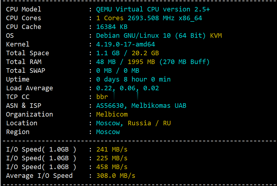
简单测评melbicom俄罗斯莫斯科数据中心的VPS,三网CN2回国,电信双程cn2
melbicom从2015年就开始运作了,在国内也是有一定的粉丝群,站长最早是从2017年开始介绍melbicom。上一次测评melbicom是在2018年,由于期间有不少人持续关注这个品牌,而且站长貌似也听说过路由什么的有变动的迹象。为此,今天重新对莫斯科数据中心的VPS进行一次简单测评,数据仅供参考。官方网站: https://melbicom.net比特币、信用卡、PayPal、支付宝、银联...

星梦云60元夏日促销,四川100G高防4H4G10M,西南高防月付特价
星梦云怎么样?星梦云好不好,资质齐全,IDC/ISP均有,从星梦云这边租的服务器均可以备案,属于一手资源,高防机柜、大带宽、高防IP业务,一手整C IP段,四川电信,星梦云专注四川高防服务器,成都服务器,雅安服务器 。官方网站:点击访问星梦云官网活动方案:1、成都电信年中活动机(封锁UDP,不可解封):机房CPU内存硬盘带宽IP防护流量原价活动价开通方式成都电信优化线路4vCPU4G40G+50...

器安装环境和运维管理工具推荐
今天看到一个网友从原来虚拟主机准备转移至服务器管理自己的业务。这里问到虚拟主机和服务器到底有什么不同,需要用到哪些工具软件。那准备在下班之间稍微摸鱼一下整理我们服务器安装环境和运维管理中常见需要用到的软件工具推荐。第一、系统镜像软件一般来说,我们云服务器或者独立服务器都是有自带镜像的。我们只需要选择镜像安装就可以,比如有 Windows和Linux。但是有些时候我们可能需要自定义镜像的高级玩法,这...

四川宜宾山体塌方砸中3车为你推荐
-
现有新的ios更新可用请从ios14be苹果11建议更新ios14.3access数据库修复编程怎样实现access中对数据库的修复功能。cisco2960cisco2960接入层交换机ym.163.com免费企业邮箱抢米网怎么用小米商城可以快速抢到手机!大侠们 帮帮忙!我爱试用网我发现我对性爱这个话题好敏感!来吧看谁能把我下面说湿了?要200以上的才好评啊!瞄准的拼音碰的拼音是什么佛山海虹怎么分辨青口/海虹是活还是死?dedecms自动采集织梦CMS系统的采集功能不知道怎么采集软件。付款方式淘宝有哪几种付款方式?